Accurately measure currents of up to 120A using TLI4971-A120T5 and STM32F373RC
Max current, max clarity

Published Aug 12, 2023
Click board™
Hall Current 8 Click - 120A
Dev. board
Fusion for ARM v8
Compiler
NECTO Studio
MCU
STM32F373RC
Engineered to excel, our Hall-effect current sensing solution, capable of measuring up to 120A, empowers industries to make informed decisions, proactively manage power consumption, and enhance overall system reliability
A
A
Hardware Overview
How does it work?
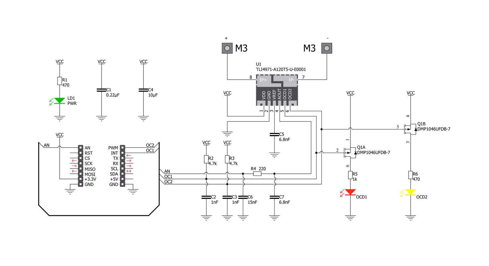
Hall Current 8 Click - 120A is based on the TLI4971-A120T5, a high-precision miniature coreless magnetic current sensor for AC and DC measurements with an analog interface and two fast overcurrent detection outputs from Infineon Technologies. The well-established Hall technology, on which the TLI4971 is based, enables accurate and highly linear measurement of currents with a full scale that depends on the chosen product variant, in this case, up to 120A. Typical applications are electrical drives and general-purpose inverters. It is suitable for fast over-current detection, which allows the control unit to switch off and protect the affected system from damage independently from the primary measurement path. The preconfigured output mode of the TLI4971-A120T5 is set to semi-differential mode. Current
flowing through the primary conductors is galvanically isolated, protecting low-voltage parts of the Click board™, as well as the host MCU, and induces a magnetic field that is differentially measured by two Hall probes. A high-performance amplifier combines the signal resulting from the differential field and the internal compensation information provided by the temperature and stress compensation unit. Then the amplifier output signal is fed into a differential output amplifier, which drives the sensor's analog output on the AN pin of the mikroBUS™ socket. In addition to the already mentioned characteristics, this Click board™ has two separate interface pins (OCD) routed to the PWM and INT pins of the mikroBUS socket. They provide fast output signals if a current exceeds a preset threshold in combination with the red and
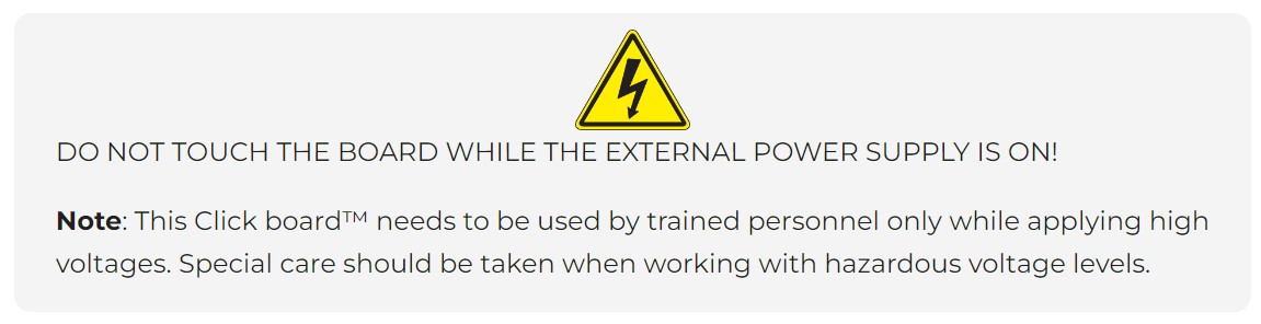
yellow LEDs marked with OCD1 and OCD2. Those pins offer a swift response thanks to independence from the main signal path. They can be used as a trap functionality to shut down the current source quickly and precisely detect mild overload conditions. Also, this Click board™ should be connected in series with the load. Two onboard terminal connectors measure the current, one terminal block for the positive and the other for the negative current input. This Click board™ can be operated only with a 3.3V logic voltage level. The board must perform appropriate logic voltage level conversion before using MCUs with different logic levels. Also, it comes equipped with a library containing functions and an example code that can be used, as a reference, for further development.

Features overview
Development board
Fusion for ARM v8 is a development board specially designed for the needs of rapid development of embedded applications. It supports a wide range of microcontrollers, such as different ARM® Cortex®-M based MCUs regardless of their number of pins, and a broad set of unique functions, such as the first-ever embedded debugger/programmer over WiFi. The development board is well organized and designed so that the end-user has all the necessary elements, such as switches, buttons, indicators, connectors, and others, in one place. Thanks to innovative manufacturing technology, Fusion for ARM v8 provides a fluid and immersive working experience, allowing access anywhere and under any
circumstances at any time. Each part of the Fusion for ARM v8 development board contains the components necessary for the most efficient operation of the same board. An advanced integrated CODEGRIP programmer/debugger module offers many valuable programming/debugging options, including support for JTAG, SWD, and SWO Trace (Single Wire Output)), and seamless integration with the Mikroe software environment. Besides, it also includes a clean and regulated power supply module for the development board. It can use a wide range of external power sources, including a battery, an external 12V power supply, and a power source via the USB Type-C (USB-C) connector.
Communication options such as USB-UART, USB HOST/DEVICE, CAN (on the MCU card, if supported), and Ethernet is also included. In addition, it also has the well-established mikroBUS™ standard, a standardized socket for the MCU card (SiBRAIN standard), and two display options for the TFT board line of products and character-based LCD. Fusion for ARM v8 is an integral part of the Mikroe ecosystem for rapid development. Natively supported by Mikroe software tools, it covers many aspects of prototyping and development thanks to a considerable number of different Click boards™ (over a thousand boards), the number of which is growing every day.

Microcontroller Overview
MCU Card / MCU
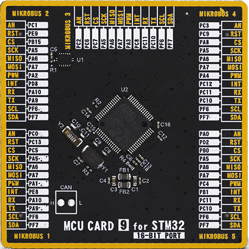
Type
8th Generation
Architecture
ARM Cortex-M4
MCU Memory (KB)
256
Silicon Vendor
STMicroelectronics
Pin count
64
RAM (Bytes)
32768
Used MCU Pins
mikroBUS™ mapper
Take a closer look
Click board™ Schematic
Step by step
Project assembly

Start by selecting your development board and Click board™. Begin with the Fusion for ARM v8 as your development board.


Track your results in real time
Application Output
1. Application Output - In Debug mode, the 'Application Output' window enables real-time data monitoring, offering direct insight into execution results. Ensure proper data display by configuring the environment correctly using the provided tutorial.

2. UART Terminal - Use the UART Terminal to monitor data transmission via a USB to UART converter, allowing direct communication between the Click board™ and your development system. Configure the baud rate and other serial settings according to your project's requirements to ensure proper functionality. For step-by-step setup instructions, refer to the provided tutorial.

3. Plot Output - The Plot feature offers a powerful way to visualize real-time sensor data, enabling trend analysis, debugging, and comparison of multiple data points. To set it up correctly, follow the provided tutorial, which includes a step-by-step example of using the Plot feature to display Click board™ readings. To use the Plot feature in your code, use the function: plot(*insert_graph_name*, variable_name);. This is a general format, and it is up to the user to replace 'insert_graph_name' with the actual graph name and 'variable_name' with the parameter to be displayed.

Software Support
Library Description
This library contains API for Hall Current 8 Click - 120A driver.
Key functions:
hallcurrent8120a_calibration- This function sets the calibration value into the offset data from context object of the TLI4971 high precision coreless current sensor on Hall Current 8 120A Clickhallcurrent8120a_get_voltage- This function reads results of AD conversion of the AN pin and converts them to proportional voltage levelhallcurrent8120a_get_current- This function reads results of AD conversion of the AN pin and converts them to proportional current level
Open Source
Code example
The complete application code and a ready-to-use project are available through the NECTO Studio Package Manager for direct installation in the NECTO Studio. The application code can also be found on the MIKROE GitHub account.
/*!
* @file main.c
* @brief Hall Current 8 120A Click Example.
*
* # Description
* This library contains API for Hall Current 8 120A Click driver.
* The library initializes and defines the ADC drivers.
* The library also includes a function for calibration,
* current measurement and overcurrent detection.
*
* The demo application is composed of two sections :
*
* ## Application Init
* Initializes ADC driver, calibrate AD conversion of the AN pin and start to write log.
*
* ## Application Task
* This is an example that demonstrates the use of the Hall Current 8 120A Click board.
* In this example, we read and display current data [A], AN pin voltage level [V].
* Results are being sent to the Usart Terminal where you can track their changes.
*
* @author Stefan Ilic
*
*/
#include "board.h"
#include "log.h"
#include "hallcurrent8120a.h"
static hallcurrent8120a_t hallcurrent8120a; /**< Hall Current 8 120A Click driver object. */
static log_t logger; /**< Logger object. */
void application_init ( void )
{
log_cfg_t log_cfg; /**< Logger config object. */
hallcurrent8120a_cfg_t hallcurrent8120a_cfg; /**< Click config object. */
/**
* Logger initialization.
* Default baud rate: 115200
* Default log level: LOG_LEVEL_DEBUG
* @note If USB_UART_RX and USB_UART_TX
* are defined as HAL_PIN_NC, you will
* need to define them manually for log to work.
* See @b LOG_MAP_USB_UART macro definition for detailed explanation.
*/
LOG_MAP_USB_UART( log_cfg );
log_init( &logger, &log_cfg );
log_info( &logger, " Application Init " );
// Click initialization.
hallcurrent8120a_cfg_setup( &hallcurrent8120a_cfg );
HALLCURRENT8120A_MAP_MIKROBUS( hallcurrent8120a_cfg, MIKROBUS_1 );
if ( ADC_ERROR == hallcurrent8120a_init( &hallcurrent8120a, &hallcurrent8120a_cfg ) )
{
log_error( &logger, " Application Init Error. " );
log_info( &logger, " Please, run program again... " );
for ( ; ; );
}
Delay_ms ( 1000 );
log_printf( &logger, "---------------------------\r\n" );
log_printf( &logger, " Turn OFF the power supply \r\n" );
Delay_ms ( 1000 );
Delay_ms ( 1000 );
Delay_ms ( 1000 );
Delay_ms ( 1000 );
Delay_ms ( 1000 );
log_printf( &logger, "---------------------------\r\n" );
log_printf( &logger, " Start Calibration \r\n" );
hallcurrent8120a_calibration ( &hallcurrent8120a );
Delay_ms ( 1000 );
log_printf( &logger, "---------------------------\r\n");
log_printf( &logger, " Turn ON the power supply \r\n" );
Delay_ms ( 1000 );
Delay_ms ( 1000 );
Delay_ms ( 1000 );
Delay_ms ( 1000 );
Delay_ms ( 1000 );
log_printf( &logger, "---------------------------\r\n");
log_printf( &logger, " Start measurements : \r\n");
log_printf( &logger, "---------------------------\r\n");
}
void application_task ( void )
{
float current = 0;
float avg_voltage = 0;
if ( HALLCURRENT8120A_OK == hallcurrent8120a_get_current ( &hallcurrent8120a, ¤t ) )
{
log_printf( &logger, " Current : %.2f [A]\r\n", current );
}
if ( HALLCURRENT8120A_OK == hallcurrent8120a_get_voltage ( &hallcurrent8120a, &avg_voltage ) )
{
log_printf( &logger, " AN pin voltage : %.2f [V]\r\n", avg_voltage );
}
log_printf( &logger, "---------------------------\r\n");
Delay_ms ( 1000 );
}
int main ( void )
{
/* Do not remove this line or clock might not be set correctly. */
#ifdef PREINIT_SUPPORTED
preinit();
#endif
application_init( );
for ( ; ; )
{
application_task( );
}
return 0;
}
// ------------------------------------------------------------------------ END


