Master the language of color like never before using VEML3328 and TM4C129XKCZAD
Experience color like never before

Published Sep 23, 2023
Click board™
Color 10 Click
Dev. board
Fusion for ARM v8
Compiler
NECTO Studio
MCU
TM4C129XKCZAD
Explore the limitless possibilities of color analysis with our cutting-edge RGB and IR light sensing solution
A
A
Hardware Overview
How does it work?
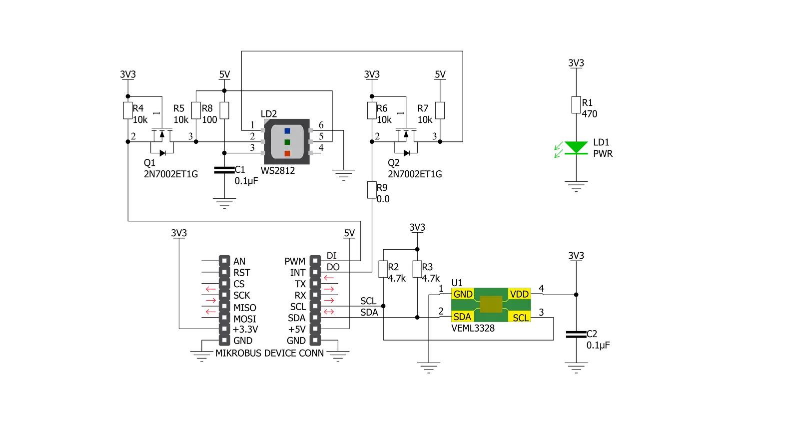
Color 10 Click is based on VEML3328, a RGB and IR light sensor from Vishay Semiconducotr. This sensor is a 16-bit, low power, high sensitivity CMOS color sensor and signal conditioning IC, that can be operated via a simple I2C commands. This sensor has many features that make it a perfect solution for small designs such as the Color 10 Click board™. One of these features is certainly its high level of integration that allows a minimal number of external components. VEML3328 provides excellent temperature compensation capability for keeping the output stable under changing temperature. The sensor’s functions are
easily operated via the simple command format of I2C (SMBus compatible) interface protocol. VEML3328 has a low operating voltage range of 2.6V to 3.6V, integrated modules, color sensor and signal conditioning IC, supports low transmittance (dark) lens design and provides 16-bit resolution for each channel (R, G, B, C, and IR). The WS2812 on Color 10 Click board™ can be used for testing purposes as well as the light source for object color detector, since VEML3328 can detect the color which WS2812 emits in R, G, B range. For clear and IR light, appropriate photodiodes should be used. The WS2812 can be controlled by data
protocol on DI and DO pins, data transfer protocol use single NZR communication mode. After the pixel power-on reset, the DI port receive data from microcontroller, the first pixel collect initial 24bit data then sent to the internal data latch, the other data which reshaping by the internal signal reshaping amplification circuit sent to the next cascade pixel through the DO port. After transmission for each pixel, the signal to reduce 24bit pixel adopt auto reshaping transmit technology, making the pixel cascade number is not limited the signal transmission, only depend on the speed of signal transmission.


Features overview
Development board
Fusion for ARM v8 is a development board specially designed for the needs of rapid development of embedded applications. It supports a wide range of microcontrollers, such as different ARM® Cortex®-M based MCUs regardless of their number of pins, and a broad set of unique functions, such as the first-ever embedded debugger/programmer over WiFi. The development board is well organized and designed so that the end-user has all the necessary elements, such as switches, buttons, indicators, connectors, and others, in one place. Thanks to innovative manufacturing technology, Fusion for ARM v8 provides a fluid and immersive working experience, allowing access anywhere and under any
circumstances at any time. Each part of the Fusion for ARM v8 development board contains the components necessary for the most efficient operation of the same board. An advanced integrated CODEGRIP programmer/debugger module offers many valuable programming/debugging options, including support for JTAG, SWD, and SWO Trace (Single Wire Output)), and seamless integration with the Mikroe software environment. Besides, it also includes a clean and regulated power supply module for the development board. It can use a wide range of external power sources, including a battery, an external 12V power supply, and a power source via the USB Type-C (USB-C) connector.
Communication options such as USB-UART, USB HOST/DEVICE, CAN (on the MCU card, if supported), and Ethernet is also included. In addition, it also has the well-established mikroBUS™ standard, a standardized socket for the MCU card (SiBRAIN standard), and two display options for the TFT board line of products and character-based LCD. Fusion for ARM v8 is an integral part of the Mikroe ecosystem for rapid development. Natively supported by Mikroe software tools, it covers many aspects of prototyping and development thanks to a considerable number of different Click boards™ (over a thousand boards), the number of which is growing every day.

Microcontroller Overview
MCU Card / MCU
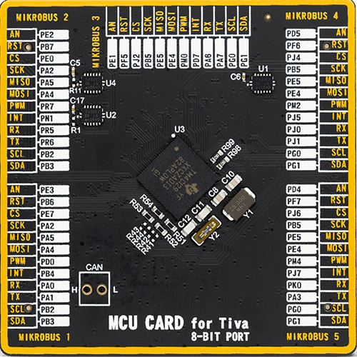
Type
8th Generation
Architecture
ARM Cortex-M4
MCU Memory (KB)
512
Silicon Vendor
Texas Instruments
Pin count
212
RAM (Bytes)
262144
Used MCU Pins
mikroBUS™ mapper
Take a closer look
Click board™ Schematic
Step by step
Project assembly

Start by selecting your development board and Click board™. Begin with the Fusion for ARM v8 as your development board.


Track your results in real time
Application Output
1. Application Output - In Debug mode, the 'Application Output' window enables real-time data monitoring, offering direct insight into execution results. Ensure proper data display by configuring the environment correctly using the provided tutorial.

2. UART Terminal - Use the UART Terminal to monitor data transmission via a USB to UART converter, allowing direct communication between the Click board™ and your development system. Configure the baud rate and other serial settings according to your project's requirements to ensure proper functionality. For step-by-step setup instructions, refer to the provided tutorial.

3. Plot Output - The Plot feature offers a powerful way to visualize real-time sensor data, enabling trend analysis, debugging, and comparison of multiple data points. To set it up correctly, follow the provided tutorial, which includes a step-by-step example of using the Plot feature to display Click board™ readings. To use the Plot feature in your code, use the function: plot(*insert_graph_name*, variable_name);. This is a general format, and it is up to the user to replace 'insert_graph_name' with the actual graph name and 'variable_name' with the parameter to be displayed.

Software Support
Library Description
This library contains API for Color 10 Click driver.
Key functions:
color10_generic_read- This function reads data from the desired registercolor10_get_color_value- This function calculates the color valuecolor10_get_color- This function identifies the color using the color value.
Open Source
Code example
The complete application code and a ready-to-use project are available through the NECTO Studio Package Manager for direct installation in the NECTO Studio. The application code can also be found on the MIKROE GitHub account.
/*!
 * \file
 * \brief Color10 Click example
 *
 * # Description
 * Color 10 Click is carrying a sensor for RGB and IR light sensing as well as
 * the RGB diode incorporated on the board which makes it good color detection
 * device when its combined with a white LED.
 *
 * The demo application is composed of two sections :
 *
 * ## Application Init
 * Initialize I2C driver.
 *
 * ## Application Task
 * This example senses orange, red, pink, purple, blue, cyan, green or yellow color
 * and IR light and print it via UART terminal.
 *
 *
 * \author MikroE Team
 *
 */
// ------------------------------------------------------------------- INCLUDES

#include "board.h"
#include "log.h"
#include "color10.h"

// ------------------------------------------------------------------ VARIABLES

static color10_t color10;
static log_t logger;

// ------------------------------------------------------- ADDITIONAL FUNCTIONS

void write_color ( void )
{
    float color_val;
    uint8_t color;

    color_val = color10_get_color_value( &color10 );
    color = color10_get_color( color_val );

    switch ( color )
    {
        case COLOR10_COLOR_ORANGE:
        {
            log_printf( &logger, "ORANGE" );
        break;
        }

        case COLOR10_COLOR_RED:
        {
            log_printf( &logger, "RED" );
        break;
        }

        case COLOR10_COLOR_PINK:
        {
            log_printf( &logger, "PINK" );
        break;
        }

        case COLOR10_COLOR_PURPLE:
        {
            log_printf( &logger, "PURPLE" );
        break;
        }

        case COLOR10_COLOR_BLUE:
        {
            log_printf( &logger, "BLUE" );
        break;
        }

        case COLOR10_COLOR_CYAN:
        {
            log_printf( &logger, "CYAN" );
        break;
        }

        case COLOR10_COLOR_GREEN:
        {
            log_printf( &logger, "GREEN" );
        break;
        }

        case COLOR10_COLOR_YELLOW:
        {
            log_printf( &logger, "YELLOW" );
        break;
        }

        default:
        {
            log_printf( &logger, "NOT DEFINED" );
        break;
        }
    }
}

// ------------------------------------------------------ APPLICATION FUNCTIONS

void application_init ( void )
{
    log_cfg_t log_cfg;
    color10_cfg_t cfg;
    uint8_t id_data;

    /**
     * Logger initialization.
     * Default baud rate: 115200
     * Default log level: LOG_LEVEL_DEBUG
     * @note If USB_UART_RX and USB_UART_TX
     * are defined as HAL_PIN_NC, you will
     * need to define them manually for log to work.
     * See @b LOG_MAP_USB_UART macro definition for detailed explanation.
     */
    LOG_MAP_USB_UART( log_cfg );
    log_init( &logger, &log_cfg );
    log_info( &logger, "---- Application Init ----" );

    //  Click initialization.

    color10_cfg_setup( &cfg );
    COLOR10_MAP_MIKROBUS( cfg, MIKROBUS_1 );
    color10_init( &color10, &cfg );
    Delay_ms ( 500 );

    if ( color10_get_id( &color10 ) == COLOR10_DEVICE_ID )
    {
         log_printf( &logger, " -DEVICE ID OK\r\n" );
    }
    else
    {
        log_printf( &logger, " -DEVICE ID ERROR\r\n" );
        for( ; ; );
    }

    color10_config( &color10, COLOR10_CFG_HIGH_DYNAMIC_RANGE_1 |
                    COLOR10_CFG_INTEGRATION_TIME_SETT_50_MS |
                    COLOR10_CFG_AUTO_MODE |
                    COLOR10_CFG_TRIGGER_NO |
                    COLOR10_CFG_POWER_ON |
                    COLOR10_CFG_GAIN_1_X1 |
                    COLOR10_CFG_GAIN_2_X1 );
    log_printf( &logger, "-----Init done------\r\n" );
    Delay_ms ( 500 );
}

void application_task ( void )
{
    uint16_t read_data;
    float color_data;

    read_data = color10_generic_read ( &color10, COLOR10_CMD_REG_IR );
    log_printf( &logger, " -IR value: %d\r\n", read_data );
    log_printf( &logger, " -Color: " );
    write_color( );

    log_printf( &logger, " ********************** \r\n" );
    Delay_ms ( 1000 );
}

int main ( void )
{
    /* Do not remove this line or clock might not be set correctly. */
    #ifdef PREINIT_SUPPORTED
    preinit();
    #endif

    application_init( );

    for ( ; ; )
    {
        application_task( );
    }

    return 0;
}


// ------------------------------------------------------------------------ END
Additional Support
Resources
Category:Optical


