Enable non-contact rotary measurements in harsh environments using AS5601 and PIC18F4680
Precision positioning: Elevate your control with magnetic sensing

Published Nov 01, 2023
Click board™
Magneto 8 Click
Dev. board
EasyPIC v7a
Compiler
NECTO Studio
MCU
PIC18F4680
Upgrade your solution capabilities by integrating magnetic position sensing, opening up possibilities for innovative applications like smart locks, thermostats, and more, with reliable position feedback
A
A
Hardware Overview
How does it work?
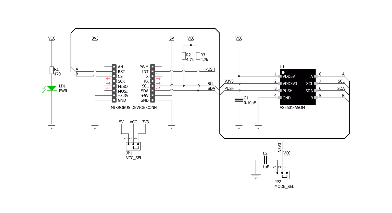
Magneto 8 Click is based on the AS5601, 12-bit programmable contactless encoder IC from AMS-AG. The AS5601 is a Hall-based rotary magnetic position encoder that converts the magnetic field component vertical to the surface of the chip into a voltage, which is used to produce incremental A/B outputs and absolute position indication. The analog signals from the Hall sensor are first amplified and filtered (before being converted by the ADC into binary data). Then, they are processed by the CORDIC block to compute the angle and magnitude of the magnetic field vector. The internal logic uses the angle values provided by the CORDIC algorithm to generate the incremental quadrature signals A and B. Additionally, the AS5601 implements a pushbutton detection function that indicates sudden
airgap changes between the AS5601 and magnet and drives the PUSH output pin high when the AS5601 detects a fast increase of the magnetic field and vice versa. The AS5601 communicates with MCU using the standard I2C 2-Wire interface with a maximum SCL frequency of 1 MHz. The I2C communication interface supports several different modes. In addition to the modes such as Standard, Fast, and Fast-Plus mode, there are three additional modes: Random/Sequential read, Byte/Page write, and Automatic increment relating to the ANGLE register. The AS5601 can be powered from a 5V supply using the on-chip LDO regulator, or it can be powered directly from a 3.3V supply. The selection can be done by positioning SMD jumpers labeled as VCC SEL to an appropriate position. In this case, there are
two voltage selection jumpers because the power pins of the AS5601 require a different configuration in the case of 3.3V and 5V power supply. In 5V operation, the second power pin must be connected to the ground via a decoupling capacitor C2. Otherwise, in 3.3V operation, the two pins must be tied together. Note that all the jumpers must be placed on the same side, or the Click board™ may become unresponsive. This Click board™ can operate with either 3.3V or 5V logic voltage levels selected via the VCC SEL jumper. This way, both 3.3V and 5V capable MCUs can use the communication lines properly. Also, this Click board™ comes equipped with a library containing easy-to-use functions and an example code that can be used as a reference for further development.


Features overview
Development board
EasyPIC v7a is the seventh generation of PIC development boards specially designed for the needs of rapid development of embedded applications. It supports a wide range of 8-bit PIC microcontrollers from Microchip and has a broad set of unique functions, such as the first-ever embedded debugger/programmer over USB-C. The development board is well organized and designed so that the end-user has all the necessary elements in one place, such as switches, buttons, indicators, connectors, and others. With four different connectors for each port, EasyPIC v7a allows you to connect accessory boards, sensors, and custom electronics more efficiently than ever. Each part of the EasyPIC v7a development board
contains the components necessary for the most efficient operation of the same board. In addition to the advanced integrated CODEGRIP programmer/debugger module, which offers many valuable programming/debugging options and seamless integration with the Mikroe software environment, the board also includes a clean and regulated power supply module for the development board. It can use various external power sources, including an external 12V power supply, 7-23V AC or 9-32V DC via DC connector/screw terminals, and a power source via the USB Type-C (USB-C) connector. Communication options such as USB-UART and RS-232 are also included, alongside the well-
established mikroBUS™ standard, three display options (7-segment, graphical, and character-based LCD), and several different DIP sockets. These sockets cover a wide range of 8-bit PIC MCUs, from PIC10F, PIC12F, PIC16F, PIC16Enh, PIC18F, PIC18FJ, and PIC18FK families. EasyPIC v7a is an integral part of the Mikroe ecosystem for rapid development. Natively supported by Mikroe software tools, it covers many aspects of prototyping and development thanks to a considerable number of different Click boards™ (over a thousand boards), the number of which is growing every day.

Microcontroller Overview
MCU Card / MCU
Architecture
PIC
MCU Memory (KB)
64
Silicon Vendor
Microchip
Pin count
40
RAM (Bytes)
3328
Used MCU Pins
mikroBUS™ mapper
Take a closer look
Click board™ Schematic
Step by step
Project assembly

Start by selecting your development board and Click board™. Begin with the EasyPIC v7a as your development board.


Track your results in real time
Application Output
1. Application Output - In Debug mode, the 'Application Output' window enables real-time data monitoring, offering direct insight into execution results. Ensure proper data display by configuring the environment correctly using the provided tutorial.

2. UART Terminal - Use the UART Terminal to monitor data transmission via a USB to UART converter, allowing direct communication between the Click board™ and your development system. Configure the baud rate and other serial settings according to your project's requirements to ensure proper functionality. For step-by-step setup instructions, refer to the provided tutorial.

3. Plot Output - The Plot feature offers a powerful way to visualize real-time sensor data, enabling trend analysis, debugging, and comparison of multiple data points. To set it up correctly, follow the provided tutorial, which includes a step-by-step example of using the Plot feature to display Click board™ readings. To use the Plot feature in your code, use the function: plot(*insert_graph_name*, variable_name);. This is a general format, and it is up to the user to replace 'insert_graph_name' with the actual graph name and 'variable_name' with the parameter to be displayed.

Software Support
Library Description
This library contains API for Magneto 8 Click driver.
Key functions:
magneto8_get_magnitude- Gets magnitude datamagneto8_get_angle_data- Gets Angle datamagneto8_psh_pin_state- Gets PSH pin state
Open Source
Code example
The complete application code and a ready-to-use project are available through the NECTO Studio Package Manager for direct installation in the NECTO Studio. The application code can also be found on the MIKROE GitHub account.
/*!
 * \file
 * \brief Magneto8 Click example
 *
 * # Description
 * This example demonstrates the use of Magneto 8 Click board.
 *
 * The demo application is composed of two sections :
 *
 * ## Application Init
 * Initializes the driver and applies the Click default configuration.
 *
 * ## Application Task
 * Reads angle and magnitude data and displays it on the USB UART every 500ms.
 *
 * \author MikroE Team
 *
 */
// ------------------------------------------------------------------- INCLUDES

#include "board.h"
#include "log.h"
#include "magneto8.h"

// ------------------------------------------------------------------ VARIABLES

static magneto8_t magneto8;
static log_t logger;

// ------------------------------------------------------ APPLICATION FUNCTIONS

void application_init ( void )
{
    log_cfg_t log_cfg;
    magneto8_cfg_t cfg;

    /**
     * Logger initialization.
     * Default baud rate: 115200
     * Default log level: LOG_LEVEL_DEBUG
     * @note If USB_UART_RX and USB_UART_TX
     * are defined as HAL_PIN_NC, you will
     * need to define them manually for log to work.
     * See @b LOG_MAP_USB_UART macro definition for detailed explanation.
     */
    LOG_MAP_USB_UART( log_cfg );
    log_init( &logger, &log_cfg );
    log_info( &logger, "---- Application Init ----" );

    //  Click initialization.

    magneto8_cfg_setup( &cfg );
    MAGNETO8_MAP_MIKROBUS( cfg, MIKROBUS_1 );
    magneto8_init( &magneto8, &cfg );

    magneto8_default_cfg( &magneto8 );
    log_printf( &logger, "--- Configuration done ---- \r\n" );
    Delay_ms ( 500 );
}

void application_task ( void )
{
    float angle;
    uint16_t mag;

    mag  = magneto8_get_magnitude( &magneto8 );
    log_printf( &logger, "Magnitude: %d \r\n", mag );

    angle = magneto8_get_angle_data( &magneto8 );
    log_printf( &logger, "Angle : %.1f deg\r\n", angle );

    log_printf( &logger, "---------------------- \r\n" );
    Delay_ms ( 500 );
}

int main ( void )
{
    /* Do not remove this line or clock might not be set correctly. */
    #ifdef PREINIT_SUPPORTED
    preinit();
    #endif

    application_init( );

    for ( ; ; )
    {
        application_task( );
    }

    return 0;
}

// ------------------------------------------------------------------------ END


