Experience the magic of precise motor control with DRV8143 and PIC18F4682
Spin to win: The key to unlocking smooth and responsive motor movements

Published Nov 01, 2023
Click board™
DC Motor 27 Click
Dev. board
EasyPIC v7a
Compiler
NECTO Studio
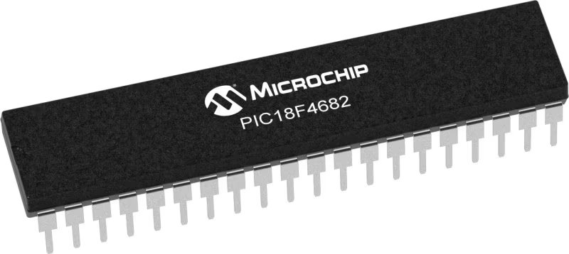
MCU
PIC18F4682
Our brushed DC motor driver puts you in command, ensuring your motors dance to your tune with precision and reliability.
A
A
Hardware Overview
How does it work?
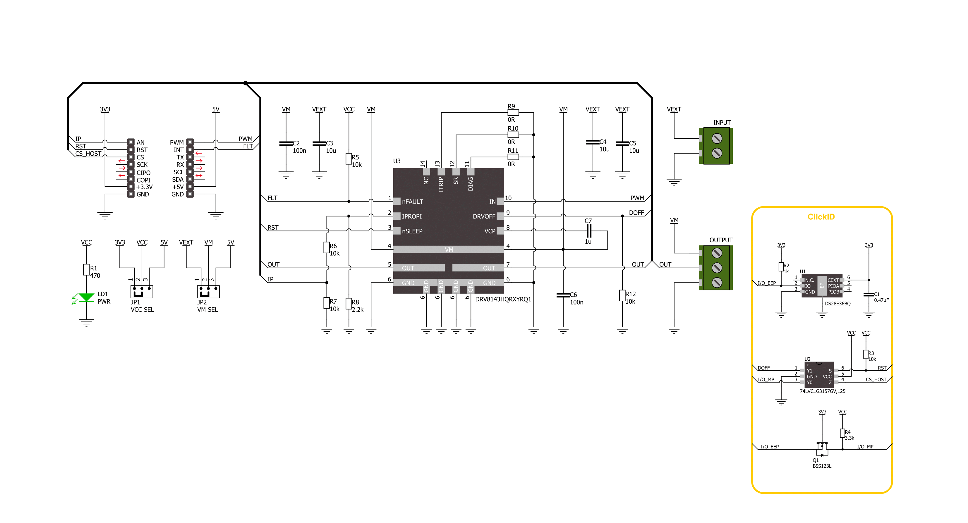
DC Motor 27 Click is based on the DRV8143, an automotive half-bridge driver with integrated current sense and diagnostic from Texas Instruments. The driver integrates an N-channel half-bridge charge pump regulator, high-side current sensing with regulation, current proportional output, and protection circuitry. It offers configurable current regulation, slew rate, spread spectrum clocking for low EMI, PWM frequency operation up to 125KHz with automatic dead time assertion, and more. The integrated current sense eliminates the need for a shunt resistor, and the driver supports a wide range of
output currents for various types of motors and loads. The device operates from a single power supply input (VM) available on the output terminal. The DC Motor 27 Click offers a VM SEL jumper that allows you to choose the power supply input from the external over the VEXT terminal and a 5V from the power rail of the mikroBUS™ socket. The EXT is set by default, so you should apply the appropriate voltage on the VEXT terminal. DC Motor 27 Click uses a static pulse-width modulated (PWM) voltage signal to communicate with the host MCU, supporting either 100% or PWM drive modes. By resetting the
driver over the RST pin, you also turn OFF a controller input for bridge Hi-Z. You can always monitor the load current over the IP pin as an analog output of the driver. The driver uses the FLT pin to inform the host MCU of faults caused by load, overvoltage, and under-voltage on the VM pin. This Click board™ can operate with either 3.3V or 5V logic voltage levels selected via the VCC SEL jumper. This way, both 3.3V and 5V capable MCUs can use the communication lines properly. Also, this Click board™ comes equipped with a library containing easy-to-use functions and an example code that can be used for further development.

Features overview
Development board
EasyPIC v7a is the seventh generation of PIC development boards specially designed for the needs of rapid development of embedded applications. It supports a wide range of 8-bit PIC microcontrollers from Microchip and has a broad set of unique functions, such as the first-ever embedded debugger/programmer over USB-C. The development board is well organized and designed so that the end-user has all the necessary elements in one place, such as switches, buttons, indicators, connectors, and others. With four different connectors for each port, EasyPIC v7a allows you to connect accessory boards, sensors, and custom electronics more efficiently than ever. Each part of the EasyPIC v7a development board
contains the components necessary for the most efficient operation of the same board. In addition to the advanced integrated CODEGRIP programmer/debugger module, which offers many valuable programming/debugging options and seamless integration with the Mikroe software environment, the board also includes a clean and regulated power supply module for the development board. It can use various external power sources, including an external 12V power supply, 7-23V AC or 9-32V DC via DC connector/screw terminals, and a power source via the USB Type-C (USB-C) connector. Communication options such as USB-UART and RS-232 are also included, alongside the well-
established mikroBUS™ standard, three display options (7-segment, graphical, and character-based LCD), and several different DIP sockets. These sockets cover a wide range of 8-bit PIC MCUs, from PIC10F, PIC12F, PIC16F, PIC16Enh, PIC18F, PIC18FJ, and PIC18FK families. EasyPIC v7a is an integral part of the Mikroe ecosystem for rapid development. Natively supported by Mikroe software tools, it covers many aspects of prototyping and development thanks to a considerable number of different Click boards™ (over a thousand boards), the number of which is growing every day.

Microcontroller Overview
MCU Card / MCU
Architecture
PIC
MCU Memory (KB)
80
Silicon Vendor
Microchip
Pin count
40
RAM (Bytes)
3328
You complete me!
Accessories
DC Gear Motor - 430RPM (3-6V) represents an all-in-one combination of a motor and gearbox, where the addition of gear leads to a reduction of motor speed while increasing the torque output. This gear motor has a spur gearbox, making it a highly reliable solution for applications with lower torque and speed requirements. The most critical parameters for gear motors are speed, torque, and efficiency, which are, in this case, 520RPM with no load and 430RPM at maximum efficiency, alongside a current of 60mA and a torque of 50g.cm. Rated for a 3-6V operational voltage range and clockwise/counterclockwise rotation direction, this motor represents an excellent solution for many functions initially performed by brushed DC motors in robotics, medical equipment, electric door locks, and much more.

Used MCU Pins
mikroBUS™ mapper
Take a closer look
Click board™ Schematic
Step by step
Project assembly

Start by selecting your development board and Click board™. Begin with the EasyPIC v7a as your development board.


Software Support
Library Description
This library contains API for DC Motor 27 Click driver.
Key functions:
dcmotor27_set_duty_cycle- DC Motor 27 sets PWM duty cycle.dcmotor27_get_flt_pin- DC Motor 27 get flt pin state.dcmotor27_set_coast- DC Motor 27 set coast mode funtion.
Open Source
Code example
The complete application code and a ready-to-use project are available through the NECTO Studio Package Manager for direct installation in the NECTO Studio. The application code can also be found on the MIKROE GitHub account.
/*!
 * @file main.c
 * @brief DC Motor 27 Click example
 *
 * # Description
 * This example demonstrates the use of the DC Motor 27 Click board by driving
 * the motor at different speeds, enabling brake and coast modes.
 *
 * The demo application is composed of two sections :
 *
 * ## Application Init
 * Initializes the driver and performs the Click default configuration.
 *
 * ## Application Task
 * Controls the motor speed by changing the PWM duty cycle every second,
 * places the motor into coast or braking mode.
 *
 * @author Stefan Ilic
 *
 */

#include "board.h"
#include "log.h"
#include "dcmotor27.h"

static dcmotor27_t dcmotor27;
static log_t logger;

void application_init ( void )
{
    log_cfg_t log_cfg;  /**< Logger config object. */
    dcmotor27_cfg_t dcmotor27_cfg;  /**< Click config object. */

    /**
     * Logger initialization.
     * Default baud rate: 115200
     * Default log level: LOG_LEVEL_DEBUG
     * @note If USB_UART_RX and USB_UART_TX
     * are defined as HAL_PIN_NC, you will
     * need to define them manually for log to work.
     * See @b LOG_MAP_USB_UART macro definition for detailed explanation.
     */
    LOG_MAP_USB_UART( log_cfg );
    log_init( &logger, &log_cfg );
    log_info( &logger, " Application Init " );

    // Click initialization.
    dcmotor27_cfg_setup( &dcmotor27_cfg );
    DCMOTOR27_MAP_MIKROBUS( dcmotor27_cfg, MIKROBUS_1 );
    if ( PWM_ERROR == dcmotor27_init( &dcmotor27, &dcmotor27_cfg ) )
    {
        log_error( &logger, " Communication init." );
        for ( ; ; );
    }
    if ( DCMOTOR27_ERROR == dcmotor27_default_cfg ( &dcmotor27 ) )
    {
        log_error( &logger, " Default configuration." );
        for ( ; ; );
    }
    log_info( &logger, " Application Task " );
}

void application_task ( void )
{
    for ( uint8_t speed_cnt = 10; speed_cnt <= 100; speed_cnt += 10 )
    {
        float speed = ( float ) speed_cnt / 100;
        dcmotor27_set_duty_cycle( &dcmotor27, speed );
        log_printf( &logger, " Motor speed %d%% \r\n", ( uint16_t ) speed_cnt );
        Delay_ms ( 1000 );
    }

    log_printf( &logger, " Motor coasting \r\n" );
    dcmotor27_set_coast( &dcmotor27, DCMOTOR27_SET_COAST_ON );
    Delay_ms ( 1000 );
    Delay_ms ( 1000 );
    dcmotor27_set_coast( &dcmotor27, DCMOTOR27_SET_COAST_OFF );

    for ( uint8_t speed_cnt = 10; speed_cnt <= 100; speed_cnt += 10 )
    {
        float speed = ( float ) speed_cnt / 100;
        dcmotor27_set_duty_cycle( &dcmotor27, speed );
        log_printf( &logger, " Motor speed %d%% \r\n", ( uint16_t ) speed_cnt );
        Delay_ms ( 1000 );
    }

    log_printf( &logger, " Motor brake is on \r\n" );
    dcmotor27_pwm_stop( &dcmotor27 );
    Delay_ms ( 1000 );
    Delay_ms ( 1000 );
    dcmotor27_pwm_start( &dcmotor27 );
}

int main ( void )
{
    /* Do not remove this line or clock might not be set correctly. */
    #ifdef PREINIT_SUPPORTED
    preinit();
    #endif

    application_init( );

    for ( ; ; )
    {
        application_task( );
    }

    return 0;
}

// ------------------------------------------------------------------------ END


