Ensure accurate object recognition with EE-SX198 and PIC18F46K40
Interruption process perfected!

Published Jun 21, 2023
Click board™
IR ECLIPSE Click
Dev. board
EasyPIC v7a
Compiler
NECTO Studio
MCU
PIC18F46K40
Our solution seamlessly integrates photointerrupter abilities into any application
A
A
Hardware Overview
How does it work?
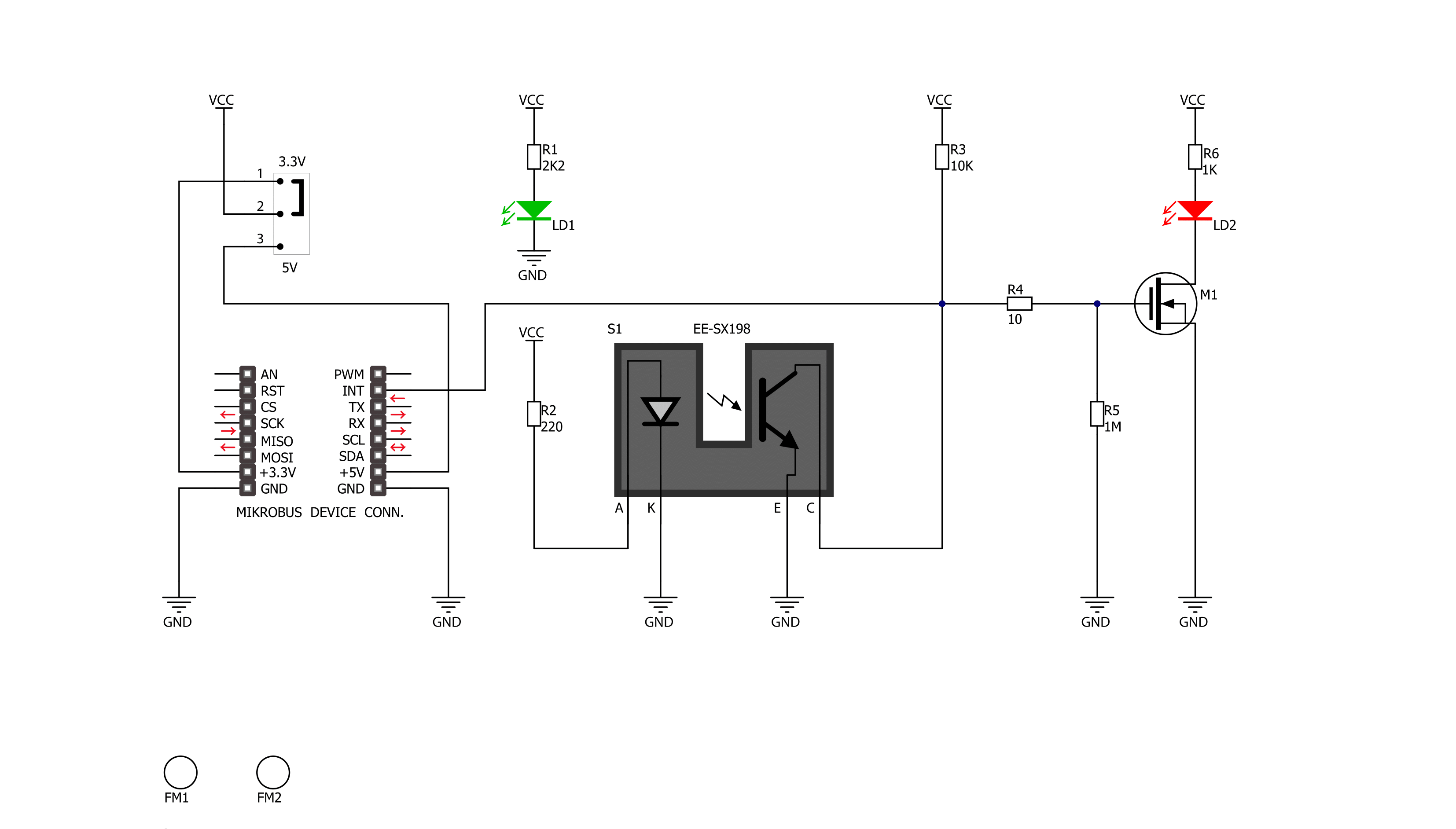
IR Eclipse Click is based on the EE-SX198, a transmissive photomicrosensor with a phototransistor output from Omron. It consists of one infrared transmitter and receiver facing each other and spaced apart by a 3mm slit. The sensor activates when an object in the gap, like a piece of paper, eclipses the transmitter beam. The object intercepts the optical beam of the emitter, thus reducing the amount of the optical energy reaching the detector. Some smaller objects do
not fully intercept the optical beam emitted by LED; therefore, some parts of the beam come to the detector and allow current flow from the phototransistor (considered noise). The IR Eclipse Click communicates with the host MCU using only the INT line of the mikroBUS™ socket. The INT pin provides information to the MCU about the presence of an object in the gap and the sensor's activity. Also, the INT LED serves as a visual indicator of the activated sensor. This Click
board™ can operate with either 3.3V or 5V logic voltage levels selected via the LOGIC LEVEL jumper. This way, both 3.3V and 5V capable MCUs can use the communication lines properly. However, the Click board™ comes equipped with a library containing easy-to-use functions and an example code that can be used, as a reference, for further development.

Features overview
Development board
EasyPIC v7a is the seventh generation of PIC development boards specially designed for the needs of rapid development of embedded applications. It supports a wide range of 8-bit PIC microcontrollers from Microchip and has a broad set of unique functions, such as the first-ever embedded debugger/programmer over USB-C. The development board is well organized and designed so that the end-user has all the necessary elements in one place, such as switches, buttons, indicators, connectors, and others. With four different connectors for each port, EasyPIC v7a allows you to connect accessory boards, sensors, and custom electronics more efficiently than ever. Each part of the EasyPIC v7a development board
contains the components necessary for the most efficient operation of the same board. In addition to the advanced integrated CODEGRIP programmer/debugger module, which offers many valuable programming/debugging options and seamless integration with the Mikroe software environment, the board also includes a clean and regulated power supply module for the development board. It can use various external power sources, including an external 12V power supply, 7-23V AC or 9-32V DC via DC connector/screw terminals, and a power source via the USB Type-C (USB-C) connector. Communication options such as USB-UART and RS-232 are also included, alongside the well-
established mikroBUS™ standard, three display options (7-segment, graphical, and character-based LCD), and several different DIP sockets. These sockets cover a wide range of 8-bit PIC MCUs, from PIC10F, PIC12F, PIC16F, PIC16Enh, PIC18F, PIC18FJ, and PIC18FK families. EasyPIC v7a is an integral part of the Mikroe ecosystem for rapid development. Natively supported by Mikroe software tools, it covers many aspects of prototyping and development thanks to a considerable number of different Click boards™ (over a thousand boards), the number of which is growing every day.

Microcontroller Overview
MCU Card / MCU
Architecture
PIC
MCU Memory (KB)
64
Silicon Vendor
Microchip
Pin count
40
RAM (Bytes)
3728
Used MCU Pins
mikroBUS™ mapper
Take a closer look
Click board™ Schematic
Step by step
Project assembly

Start by selecting your development board and Click board™. Begin with the EasyPIC v7a as your development board.


Software Support
Library Description
This library contains API for IR ECLIPSE Click driver.
Key functions:
ireclipse_int_status- Detecting states of IR beam from EE-SX198 photo interrupter sensor
Open Source
Code example
The complete application code and a ready-to-use project are available through the NECTO Studio Package Manager for direct installation in the NECTO Studio. The application code can also be found on the MIKROE GitHub account.
/*!
 * \file
 * \brief Ir Eclipse Click example
 *
 * # Description
 * This is an example of IR ECLIPSE Click board
 *
 * The demo application is composed of two sections :
 *
 * ## Application Init
 * Configuring Clicks and log objects.
 *
 * ## Application Task
 * This is a example which demonstrates the use of IR eclipse Click board.
 * When the beam from the transmitter is eclipsed by placing an object in
 * the gap ( like a piece of paper ), when the sensor is triggered, the
 * counter is incremented by one. Results are being sent to the Usart
 * Terminal where you can track their changes. Data logs on usb uart
 * when the sensor is triggered.
 *
 *
 * \author MikroE Team
 *
 */
// ------------------------------------------------------------------- INCLUDES

#include "board.h"
#include "log.h"
#include "ireclipse.h"

// ------------------------------------------------------------------ VARIABLES

static ireclipse_t ireclipse;
static log_t logger;
uint8_t state_new;
uint8_t state_old;
uint16_t n_cnt;

// ------------------------------------------------------- ADDITIONAL FUNCTIONS


// ------------------------------------------------------ APPLICATION FUNCTIONS

void application_init ( void )
{
    log_cfg_t log_cfg;
    ireclipse_cfg_t cfg;

    /**
     * Logger initialization.
     * Default baud rate: 115200
     * Default log level: LOG_LEVEL_DEBUG
     * @note If USB_UART_RX and USB_UART_TX
     * are defined as HAL_PIN_NC, you will
     * need to define them manually for log to work.
     * See @b LOG_MAP_USB_UART macro definition for detailed explanation.
     */
    LOG_MAP_USB_UART( log_cfg );
    log_init( &logger, &log_cfg );
    log_printf(&logger, "- Application Init -\r\n");

    //  Click initialization.

    ireclipse_cfg_setup( &cfg );
    IRECLIPSE_MAP_MIKROBUS( cfg, MIKROBUS_1 );
    ireclipse_init( &ireclipse, &cfg );
    log_printf( &logger, "--------------------\r\n" );
    log_printf( &logger, "   Start counting:  \r\n" );
    log_printf( &logger, "--------------------\r\n" );

    n_cnt = IRECLIPSE_START_CNT_VAL;
    state_old = IRECLIPSE_LOW;
    state_new = IRECLIPSE_LOW;
}

void application_task ( void )
{
    state_new = ireclipse_int_status( &ireclipse );

    if ( ( state_new == IRECLIPSE_HIGH ) && ( state_old == IRECLIPSE_LOW ) )
    {
        state_old = IRECLIPSE_HIGH;
        log_printf( &logger, "  Counter = %d \r\n", ++n_cnt );

    }

    if ( ( state_new == IRECLIPSE_LOW ) && ( state_old == IRECLIPSE_HIGH ) )
    {
        log_printf( &logger, "--------------------\r\n" );
        state_old = IRECLIPSE_LOW;
    }
}

int main ( void )
{
    /* Do not remove this line or clock might not be set correctly. */
    #ifdef PREINIT_SUPPORTED
    preinit();
    #endif

    application_init( );

    for ( ; ; )
    {
        application_task( );
    }

    return 0;
}


// ------------------------------------------------------------------------ END
Additional Support
Resources
Category:Optical


