Manage and regulate power efficiently using MAX25232 and PIC18LF45K42
Ensure a consistent and reliable power supply

Published Nov 13, 2023
Click board™
Step Down 8 Click
Dev. board
EasyPIC v7a
Compiler
NECTO Studio
MCU
PIC18LF45K42
Our DC-DC converter promises not just a reduction in voltage but a surge in performance for your electronic applications.
A
A
Hardware Overview
How does it work?
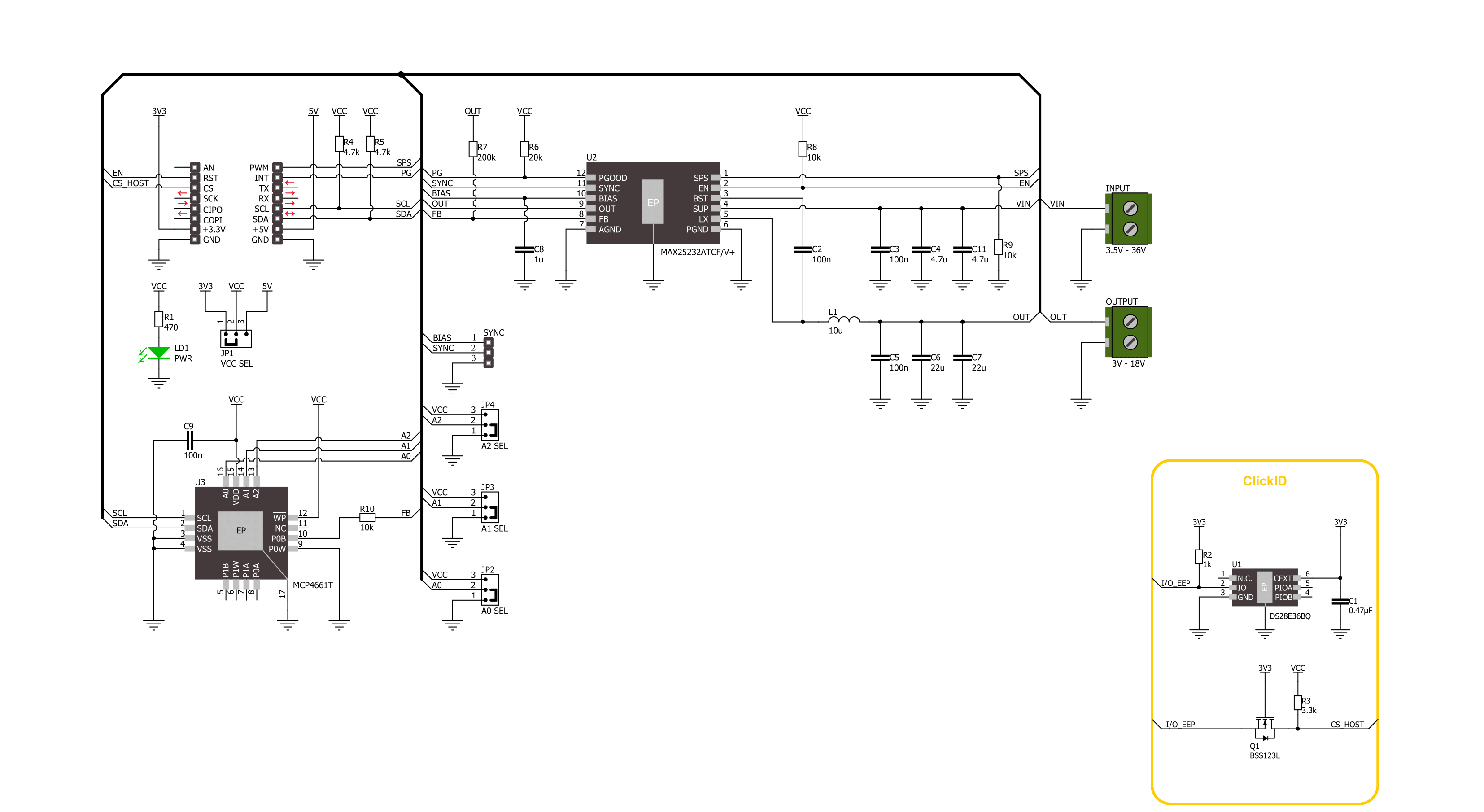
Step Down 8 Click is based on the MAX25232, a mini buck converter from Analog Devices. The MAX25232 features an under-voltage lockout, a soft-start timer, an on-chip oscillator, skip-mode operation, output-voltage overshoot protection, thermal-overload protection, and many more features. This current-mode-controlled buck converter operates at a 2.1MHz frequency, which guarantees no AM band interference, while it can also operate at 400KHz for minimum switching losses and maximum efficiency. While maintaining a 3A output current, it can stay in dropout by running at a 99% duty cycle. Voltage quality can be monitored by the host MCU. To set the output voltage, this Click board™ uses the MCP4661, an 8-bit I2C digital potentiometer with non-volatile memory. It comes with 256 resistors
and 257 wiper positions, while the last position is stored in an EEPROM. By setting the wiper value of resistance, you can set the output voltage of the MAX25232 converter available on the VOUT terminal. The Step Down 8 Click also features an unpopulated 3-pin header that allows you to set an operation mode. If you connect the SYNC pin to a GND or leave it unconnected, the device operates in a highly efficient pulse-skipping mode. If you connect SYNC to a BIAS pin or apply a clock to it, the device is in a forced-PWM mode (FPWM). Switching of modes can be done during the operation. Step Down 8 Click uses a standard 2-Wire I2C interface of the MCP4661 to communicate with the host MCU, supporting 100KHz, 400KHz, and 3.4MHz frequencies. The I2C address can be set over the ADDR SEL jumpers,
where the 0 position is selected by default. There is an EN enable pin to enable the converter and a PG power good pin that allows you to monitor the voltage quality. The Spread-Spectrum feature is an option that can be enabled over the SPS pin, offered to improve the EMI performance of the device. It does not interfere with the external clock applied to the SYNC pin. This Click board™ can operate with either 3.3V or 5V logic voltage levels selected via the VCC SEL jumper. This way, both 3.3V and 5V capable MCUs can use the communication lines properly. Also, this Click board™ comes equipped with a library containing easy-to-use functions and an example code that can be used as a reference for further development.

Features overview
Development board
EasyPIC v7a is the seventh generation of PIC development boards specially designed for the needs of rapid development of embedded applications. It supports a wide range of 8-bit PIC microcontrollers from Microchip and has a broad set of unique functions, such as the first-ever embedded debugger/programmer over USB-C. The development board is well organized and designed so that the end-user has all the necessary elements in one place, such as switches, buttons, indicators, connectors, and others. With four different connectors for each port, EasyPIC v7a allows you to connect accessory boards, sensors, and custom electronics more efficiently than ever. Each part of the EasyPIC v7a development board
contains the components necessary for the most efficient operation of the same board. In addition to the advanced integrated CODEGRIP programmer/debugger module, which offers many valuable programming/debugging options and seamless integration with the Mikroe software environment, the board also includes a clean and regulated power supply module for the development board. It can use various external power sources, including an external 12V power supply, 7-23V AC or 9-32V DC via DC connector/screw terminals, and a power source via the USB Type-C (USB-C) connector. Communication options such as USB-UART and RS-232 are also included, alongside the well-
established mikroBUS™ standard, three display options (7-segment, graphical, and character-based LCD), and several different DIP sockets. These sockets cover a wide range of 8-bit PIC MCUs, from PIC10F, PIC12F, PIC16F, PIC16Enh, PIC18F, PIC18FJ, and PIC18FK families. EasyPIC v7a is an integral part of the Mikroe ecosystem for rapid development. Natively supported by Mikroe software tools, it covers many aspects of prototyping and development thanks to a considerable number of different Click boards™ (over a thousand boards), the number of which is growing every day.

Microcontroller Overview
MCU Card / MCU
Architecture
PIC
MCU Memory (KB)
32
Silicon Vendor
Microchip
Pin count
40
RAM (Bytes)
2048
Used MCU Pins
mikroBUS™ mapper
Take a closer look
Click board™ Schematic
Step by step
Project assembly

Start by selecting your development board and Click board™. Begin with the EasyPIC v7a as your development board.


Track your results in real time
Application Output
1. Application Output - In Debug mode, the 'Application Output' window enables real-time data monitoring, offering direct insight into execution results. Ensure proper data display by configuring the environment correctly using the provided tutorial.

2. UART Terminal - Use the UART Terminal to monitor data transmission via a USB to UART converter, allowing direct communication between the Click board™ and your development system. Configure the baud rate and other serial settings according to your project's requirements to ensure proper functionality. For step-by-step setup instructions, refer to the provided tutorial.

3. Plot Output - The Plot feature offers a powerful way to visualize real-time sensor data, enabling trend analysis, debugging, and comparison of multiple data points. To set it up correctly, follow the provided tutorial, which includes a step-by-step example of using the Plot feature to display Click board™ readings. To use the Plot feature in your code, use the function: plot(*insert_graph_name*, variable_name);. This is a general format, and it is up to the user to replace 'insert_graph_name' with the actual graph name and 'variable_name' with the parameter to be displayed.

Software Support
Library Description
This library contains API for Step Down 8 Click driver.
Key functions:
stepdown8_set_en_pin- Step Down 8 set EN pin state function.stepdown8_set_wiper_pos- Step Down 8 set wiper position.stepdown8_set_output- Step Down 8 set output voltage.
Open Source
Code example
The complete application code and a ready-to-use project are available through the NECTO Studio Package Manager for direct installation in the NECTO Studio. The application code can also be found on the MIKROE GitHub account.
/*!
 * @file main.c
 * @brief Step Down 8 Click example
 *
 * # Description
 * This library contains API for the Step Down 8 Click driver.
 * This driver provides the functions to set the output voltage treshold.
 *
 * The demo application is composed of two sections :
 *
 * ## Application Init
 * Initialization of I2C module and log UART.
 * After driver initialization, default settings sets output voltage to 3 V.
 *
 * ## Application Task
 * This example demonstrates the use of the Step Down 8 Click board™ by changing
 * output voltage every 2 seconds starting from 3 V up to 18 V.
 *
 * @author Stefan Ilic
 *
 */

#include "board.h"
#include "log.h"
#include "stepdown8.h"

static stepdown8_t stepdown8;
static log_t logger;

void application_init ( void )
{
    log_cfg_t log_cfg;  /**< Logger config object. */
    stepdown8_cfg_t stepdown8_cfg;  /**< Click config object. */

    /**
     * Logger initialization.
     * Default baud rate: 115200
     * Default log level: LOG_LEVEL_DEBUG
     * @note If USB_UART_RX and USB_UART_TX
     * are defined as HAL_PIN_NC, you will
     * need to define them manually for log to work.
     * See @b LOG_MAP_USB_UART macro definition for detailed explanation.
     */
    LOG_MAP_USB_UART( log_cfg );
    log_init( &logger, &log_cfg );
    log_info( &logger, " Application Init " );

    // Click initialization.
    stepdown8_cfg_setup( &stepdown8_cfg );
    STEPDOWN8_MAP_MIKROBUS( stepdown8_cfg, MIKROBUS_1 );
    if ( I2C_MASTER_ERROR == stepdown8_init( &stepdown8, &stepdown8_cfg ) )
    {
        log_error( &logger, " Communication init." );
        for ( ; ; );
    }

    if ( STEPDOWN8_ERROR == stepdown8_default_cfg ( &stepdown8 ) )
    {
        log_error( &logger, " Default configuration." );
        for ( ; ; );
    }

    log_info( &logger, " Application Task " );
}

void application_task ( void )
{
    for ( uint8_t n_cnt = STEPDOWN8_MIN_OUTPUT; n_cnt <= STEPDOWN8_MAX_OUTPUT; n_cnt++ )
    {
        stepdown8_set_output( &stepdown8, ( float ) n_cnt );
        log_printf( &logger, " Output voltage %d V\r\n", ( uint16_t ) n_cnt );
        Delay_ms ( 1000 );
        Delay_ms ( 1000 );
    }
}

int main ( void )
{
    /* Do not remove this line or clock might not be set correctly. */
    #ifdef PREINIT_SUPPORTED
    preinit();
    #endif

    application_init( );

    for ( ; ; )
    {
        application_task( );
    }

    return 0;
}

// ------------------------------------------------------------------------ END


