Find your true direction with MMC5883MA and PIC18LF47K42
Enhanced directional awareness
Published Sep 12, 2023
Click board™
Compass 3 Click
Dev. board
EasyPIC v7a
Compiler
NECTO Studio
MCU
PIC18LF47K42
Our digital compass solution offers precise navigation capabilities, making it a valuable tool for various orientation-sensitive applications
A
A
Hardware Overview
How does it work?
Compass 3 Click is based on the MMC5883MA, a complete 3-axis magnetic sensor with on-chip signal processing and an integrated I2C bus suitable for use in various applications from MEMSIC. The device eliminates needing A/D converters or timing resources by directly connecting to a microprocessor. It can measure magnetic fields within the full-scale range of ±8Gauss (G), with 0.25mG per LSB resolution at 16-bit operation mode and 0.4mG total RMS noise level. It enables heading accuracy of ±1° in electronic compass applications. An integrated
SET/RESET function eliminates errors due to Null Field output change with temperature. Temperature information from the integrated temperature sensor is available over the I2C Interface. The SET/RESET function can be performed for each measurement periodically or when the temperature changes by a predetermined amount, as the specific application requires. In addition, the SET/RESET function clears the sensors of any residual magnetic polarization resulting from exposure to strong external magnets. The MMC5883MA is packaged
in a low-profile LGA package (3.0 x 3.0 x 1.0 mm) with a wide operating temperature range. The MMC5883MA provides an I2C digital output with 400 kHz, fast mode operation. This Click board™ can be operated only with a 3.3V logic voltage level. The board must perform appropriate logic voltage level conversion before using MCUs with different logic levels. Also, it comes equipped with a library containing functions and an example code that can be used as a reference for further development.


Features overview
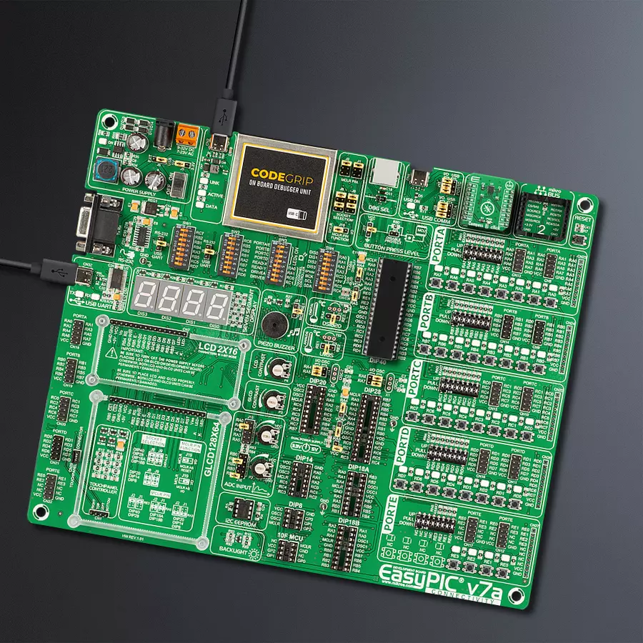
Development board
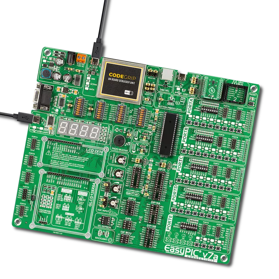
EasyPIC v7a is the seventh generation of PIC development boards specially designed for the needs of rapid development of embedded applications. It supports a wide range of 8-bit PIC microcontrollers from Microchip and has a broad set of unique functions, such as the first-ever embedded debugger/programmer over USB-C. The development board is well organized and designed so that the end-user has all the necessary elements in one place, such as switches, buttons, indicators, connectors, and others. With four different connectors for each port, EasyPIC v7a allows you to connect accessory boards, sensors, and custom electronics more efficiently than ever. Each part of the EasyPIC v7a development board
contains the components necessary for the most efficient operation of the same board. In addition to the advanced integrated CODEGRIP programmer/debugger module, which offers many valuable programming/debugging options and seamless integration with the Mikroe software environment, the board also includes a clean and regulated power supply module for the development board. It can use various external power sources, including an external 12V power supply, 7-23V AC or 9-32V DC via DC connector/screw terminals, and a power source via the USB Type-C (USB-C) connector. Communication options such as USB-UART and RS-232 are also included, alongside the well-
established mikroBUS™ standard, three display options (7-segment, graphical, and character-based LCD), and several different DIP sockets. These sockets cover a wide range of 8-bit PIC MCUs, from PIC10F, PIC12F, PIC16F, PIC16Enh, PIC18F, PIC18FJ, and PIC18FK families. EasyPIC v7a is an integral part of the Mikroe ecosystem for rapid development. Natively supported by Mikroe software tools, it covers many aspects of prototyping and development thanks to a considerable number of different Click boards™ (over a thousand boards), the number of which is growing every day.

Microcontroller Overview
MCU Card / MCU
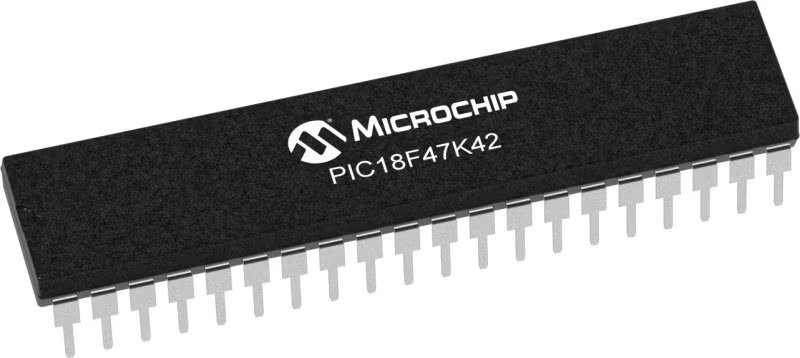
Architecture
PIC
MCU Memory (KB)
128
Silicon Vendor
Microchip
Pin count
40
RAM (Bytes)
8192
Used MCU Pins
mikroBUS™ mapper
Take a closer look
Click board™ Schematic

Step by step
Project assembly

Start by selecting your development board and Click board™. Begin with the EasyPIC v7a as your development board.


Track your results in real time
Application Output
1. Application Output - In Debug mode, the 'Application Output' window enables real-time data monitoring, offering direct insight into execution results. Ensure proper data display by configuring the environment correctly using the provided tutorial.

2. UART Terminal - Use the UART Terminal to monitor data transmission via a USB to UART converter, allowing direct communication between the Click board™ and your development system. Configure the baud rate and other serial settings according to your project's requirements to ensure proper functionality. For step-by-step setup instructions, refer to the provided tutorial.

3. Plot Output - The Plot feature offers a powerful way to visualize real-time sensor data, enabling trend analysis, debugging, and comparison of multiple data points. To set it up correctly, follow the provided tutorial, which includes a step-by-step example of using the Plot feature to display Click board™ readings. To use the Plot feature in your code, use the function: plot(*insert_graph_name*, variable_name);. This is a general format, and it is up to the user to replace 'insert_graph_name' with the actual graph name and 'variable_name' with the parameter to be displayed.

Software Support
Library Description
This library contains API for Compass 3 Click driver.
Key functions:
compass3_full_measurement- Measures magnetic field surrounding the devicecompass3_read_temp- Function is used to measure temperaturecompass3_check_int- Function checks interrupt occurence
Open Source
Code example
The complete application code and a ready-to-use project are available through the NECTO Studio Package Manager for direct installation in the NECTO Studio. The application code can also be found on the MIKROE GitHub account.
/*!
 * \file
 * \brief Compass3 Click example
 *
 * # Description
 * This demoapp measures the magnetic field surrounding the device.
 *
 * The demo application is composed of two sections :
 *
 * ## Application Init
 * Initalizes I2C driver and Click driver, performs check, applies default
 * setup and writes an initial log.
 *
 * ## Application Task
 *  This example demonstrates the use of
 * Compass 3 Click board by measuring the magnetic field surrounding the device.
 *
 * \author Jovan Stajkovic
 *
 */
// ------------------------------------------------------------------- INCLUDES

#include "board.h"
#include "log.h"
#include "compass3.h"

// ------------------------------------------------------------------ VARIABLES

static compass3_t compass3;
static log_t logger;
static float x_val;
static float y_val;
static float z_val;
static uint8_t test_val;

// ------------------------------------------------------ APPLICATION FUNCTIONS

void application_init ( void )
{
    log_cfg_t log_cfg;
    compass3_cfg_t cfg;

    /**
     * Logger initialization.
     * Default baud rate: 115200
     * Default log level: LOG_LEVEL_DEBUG
     * @note If USB_UART_RX and USB_UART_TX
     * are defined as HAL_PIN_NC, you will
     * need to define them manually for log to work.
     * See @b LOG_MAP_USB_UART macro definition for detailed explanation.
     */
    LOG_MAP_USB_UART( log_cfg );
    log_init( &logger, &log_cfg );
    log_info( &logger, "---- Application Init ----" );

    //  Click initialization.

    compass3_cfg_setup( &cfg );
    COMPASS3_MAP_MIKROBUS( cfg, MIKROBUS_1 );
    compass3_init( &compass3, &cfg );
    Delay_ms ( 100 );

    compass3_generic_read( &compass3, COMPASS3_DEVICE_ID, &test_val, 1 );

    if ( test_val == COMPASS3_DEVICE_ID_NUM )
    {
        log_printf( &logger, "--------------------\r\n" );
        log_printf( &logger, "   Compass 3 Click  \r\n" );
        log_printf( &logger, "--------------------\r\n" );
    }
    else
    {
        log_printf( &logger, "   Fatal error!!!   \r\n" );
        for ( ; ; );
    }

    compass3_default_cfg ( &compass3 );
    Delay_ms ( 100 );
}

void application_task ( void )
{
    if ( compass3_check_int( &compass3 ) == COMPASS3_INTERRUPT )
    {
        compass3_full_measurement ( &compass3, &x_val, &y_val, &z_val );

        log_printf( &logger,"  X-axis : %.2f mG\r\n", x_val );
        log_printf( &logger,"  Y-axis : %.2f mG\r\n", y_val );
        log_printf( &logger,"  Z-axis : %.2f mG\r\n", z_val );

        Delay_ms ( 1000 );
        log_printf( &logger, "--------------------\r\n" );
    }
}

int main ( void )
{
    /* Do not remove this line or clock might not be set correctly. */
    #ifdef PREINIT_SUPPORTED
    preinit();
    #endif

    application_init( );

    for ( ; ; )
    {
        application_task( );
    }

    return 0;
}

// ------------------------------------------------------------------------ END