Measure both linear and rotational movements of a magnet with AS5510 and PIC18LF4610
Revolutionize magnetic sensing

Published Nov 01, 2023
Click board™
Magneto 11 Click
Dev. board
EasyPIC v7
Compiler
NECTO Studio
MCU
PIC18LF4610
Unlock a world of possibilities with our magnetic sensing solution, capable of seamlessly tracking magnetic fields, magnet positioning, and angle of rotation for enhanced control and automation
A
A
Hardware Overview
How does it work?
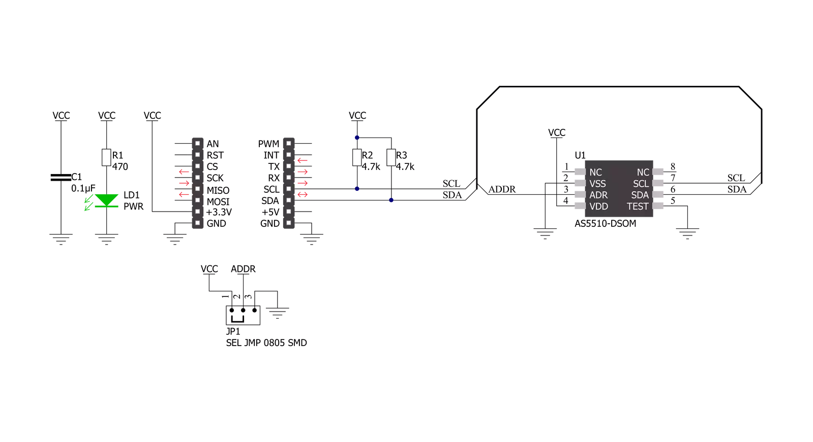
Magneto 11 Click is based on the AS5510, a 10-bit linear position sensor with digital position (interface) output from ams AG. The AS5510 can measure the absolute position of lateral movement in combination with a diametrical two-pole magnet. The sensor needs a simple 2-pole magnet to measure a lateral movement, and the measured distance depends on the magnet geometry. Depending on the magnet size, a lateral stroke of 0.5mm ~ 2mm can be measured with air gaps around 1.0mm. With stronger magnets, even higher lateral strokes and air gaps are possible. The AS5510 comes in a version of a ±50mT full-scale sensing range to deliver the highest
reliability and durability in contactless position measurements. By selecting different measurement ranges, it is possible to choose different sensitivity values; the default sensitivity value of the AS5510 is 97.66µT/LSB. It also features a Power-Down mode that helps save energy and maximize run-time in battery-powered applications. Magneto 11 Click communicates with MCU using the standard I2C 2-Wire interface for switching between four different sensitivity ranges and for simple data transmission to an MCU, supporting Fast Mode Plus operation with a clock frequency up to 1MHz. The absolute position is measured with a resolution of 10 bit = 1024
positions, and it is provided as a digital value on the serial interface. Besides, the AS5510 allows choosing the least significant bit (LSB) of its I2C slave address using the SMD jumper labeled ADDR SEL. The selection can be made by positioning the SMD jumper to an appropriate position marked as 1 or 0. This Click board™ can be operated only with a 3.3V logic voltage level. The board must perform appropriate logic voltage level conversion before using MCUs with different logic levels. Also, it comes equipped with a library containing functions and an example code that can be used as a reference for further development.


Features overview
Development board
EasyPIC v7 is the seventh generation of PIC development boards specially designed to develop embedded applications rapidly. It supports a wide range of 8-bit PIC microcontrollers from Microchip and has a broad set of unique functions, such as a powerful onboard mikroProg programmer and In-Circuit debugger over USB-B. The development board is well organized and designed so that the end-user has all the necessary elements in one place, such as switches, buttons, indicators, connectors, and others. With four different connectors for each port, EasyPIC v7 allows you to connect accessory boards, sensors, and custom electronics more efficiently than ever. Each part of
the EasyPIC v7 development board contains the components necessary for the most efficient operation of the same board. An integrated mikroProg, a fast USB 2.0 programmer with mikroICD hardware In-Circuit Debugger, offers many valuable programming/debugging options and seamless integration with the Mikroe software environment. Besides it also includes a clean and regulated power supply block for the development board. It can use various external power sources, including an external 12V power supply, 7-23V AC or 9-32V DC via DC connector/screw terminals, and a power source via the USB Type-B (USB-B) connector. Communication options such as
USB-UART and RS-232 are also included, alongside the well-established mikroBUS™ standard, three display options (7-segment, graphical, and character-based LCD), and several different DIP sockets. These sockets cover a wide range of 8-bit PIC MCUs, from PIC10F, PIC12F, PIC16F, PIC16Enh, PIC18F, PIC18FJ, and PIC18FK families. EasyPIC v7 is an integral part of the Mikroe ecosystem for rapid development. Natively supported by Mikroe software tools, it covers many aspects of prototyping and development thanks to a considerable number of different Click boards™ (over a thousand boards), the number of which is growing every day.

Microcontroller Overview
MCU Card / MCU

Architecture
PIC
MCU Memory (KB)
64
Silicon Vendor
Microchip
Pin count
40
RAM (Bytes)
3968
Used MCU Pins
mikroBUS™ mapper
Take a closer look
Click board™ Schematic
Step by step
Project assembly

Start by selecting your development board and Click board™. Begin with the EasyPIC v7 as your development board.


Track your results in real time
Application Output
1. Application Output - In Debug mode, the 'Application Output' window enables real-time data monitoring, offering direct insight into execution results. Ensure proper data display by configuring the environment correctly using the provided tutorial.

2. UART Terminal - Use the UART Terminal to monitor data transmission via a USB to UART converter, allowing direct communication between the Click board™ and your development system. Configure the baud rate and other serial settings according to your project's requirements to ensure proper functionality. For step-by-step setup instructions, refer to the provided tutorial.

3. Plot Output - The Plot feature offers a powerful way to visualize real-time sensor data, enabling trend analysis, debugging, and comparison of multiple data points. To set it up correctly, follow the provided tutorial, which includes a step-by-step example of using the Plot feature to display Click board™ readings. To use the Plot feature in your code, use the function: plot(*insert_graph_name*, variable_name);. This is a general format, and it is up to the user to replace 'insert_graph_name' with the actual graph name and 'variable_name' with the parameter to be displayed.

Software Support
Library Description
This library contains API for Magneto 11 Click driver.
Key functions:
magneto11_get_magnetic_field- This function reads the magnetic field strength in mTmagneto11_set_sensitivity- This function writes specified data to the sensitivity registermagneto11_set_config- This function writes specified data to the config register
Open Source
Code example
The complete application code and a ready-to-use project are available through the NECTO Studio Package Manager for direct installation in the NECTO Studio. The application code can also be found on the MIKROE GitHub account.
/*!
 * @file main.c
 * @brief Magneto11 Click example
 *
 * # Description
 * This example demonstrates the use of Magneto 11 Click board by reading and displaying
 * the magnetic field strength value.
 *
 * The demo application is composed of two sections :
 *
 * ## Application Init
 * Initializes the driver and performs the Click default configuration.
 *
 * ## Application Task
 * Reads the magnetic field strength value in milliTesla and displays the results on the USB UART
 * every 200ms approximately.
 *
 * @author Stefan Filipovic
 *
 */

#include "board.h"
#include "log.h"
#include "magneto11.h"

static magneto11_t magneto11;
static log_t logger;

void application_init ( void )
{
    log_cfg_t log_cfg;  /**< Logger config object. */
    magneto11_cfg_t magneto11_cfg;  /**< Click config object. */

    /**
     * Logger initialization.
     * Default baud rate: 115200
     * Default log level: LOG_LEVEL_DEBUG
     * @note If USB_UART_RX and USB_UART_TX
     * are defined as HAL_PIN_NC, you will
     * need to define them manually for log to work.
     * See @b LOG_MAP_USB_UART macro definition for detailed explanation.
     */
    LOG_MAP_USB_UART( log_cfg );
    log_init( &logger, &log_cfg );
    log_info( &logger, " Application Init " );

    // Click initialization.
    magneto11_cfg_setup( &magneto11_cfg );
    MAGNETO11_MAP_MIKROBUS( magneto11_cfg, MIKROBUS_1 );
    if ( I2C_MASTER_ERROR == magneto11_init( &magneto11, &magneto11_cfg ) )
    {
        log_error( &logger, " Communication init." );
        for ( ; ; );
    }

    if ( MAGNETO11_ERROR == magneto11_default_cfg ( &magneto11 ) )
    {
        log_error( &logger, " Default configuration." );
        for ( ; ; );
    }

    log_info( &logger, " Application Task " );
}

void application_task ( void )
{
    float magnetic_field;
    if ( MAGNETO11_OK == magneto11_get_magnetic_field ( &magneto11, &magnetic_field ) )
    {
        log_printf ( &logger, " Magnetic Field: %.3f mT \r\n\n", magnetic_field );
        Delay_ms ( 200 );
    }
}

int main ( void )
{
    /* Do not remove this line or clock might not be set correctly. */
    #ifdef PREINIT_SUPPORTED
    preinit();
    #endif

    application_init( );

    for ( ; ; )
    {
        application_task( );
    }

    return 0;
}

// ------------------------------------------------------------------------ END


