Achieve unparalleled mastery of Earth's magnetic forces with our geomagnetic solution based on BMM150 and ATmega324P
Unlocking Earth's secrets

Published Sep 13, 2023
Click board™
GeoMagnetic Click
Dev. board
EasyAVR v7
Compiler
NECTO Studio
MCU
ATmega324P
Our cutting-edge geomagnetic sensor is your gateway to understanding Earth's magnetic field with precision. It empowers you to explore geophysical phenomena, enhance navigation systems, and conduct environmental monitoring with unparalleled accuracy.
A
A
Hardware Overview
How does it work?
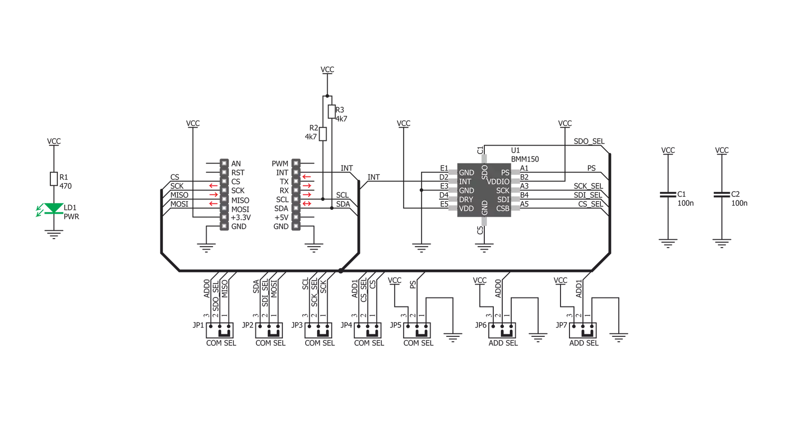
GeoMagnetic Click is based on the BMM150, a three-axis geomagnetic sensor from Bosh Sensortec. Featuring the proprietary FlipCore technology from Bosch, low power consumption, and noise, as well as thermally compensated measurements, this device is specially tuned and tailored to be used in demanding 3-axis mobile applications. The BMM150 module is able to work in four power modes: Power Off mode, Suspend mode, Sleep mode and Active mode. The overall power consumption is greatly affected by the selection of power modes. All modes except the Power Off mode can be set by programming the appropriate registers. Additionally, while working in Active mode, the power consumption depends on the measurement rate, which can be either timed with the programmed output data rate (Normal mode) or forced by the user (Forced mode). The sensor output noise is processed by the internal integrator, so setting more measurement repetitions for the same axis will yield output results with less noise. This also affects the overall power consumption in the Active mode. There are four interrupt engines available on this device: low threshold, high
threshold and overflow and data ready (DRDY). Every interrupt engine can be enabled independently. If the interrupt is enabled, it will set the corresponding status bit in the status register. For this interrupt to appear on the INT pin of the BMM150 IC, a corresponding bit should be set in the configuration register. This pin is routed to the mikroBUS™ INT pin and can be used for triggering external events. Data ready pin is not physically available on the click board™, but still, its status bit can be read from the status register. The temperature compensation is based on a hall plate sensor measurement. This IC outputs raw values for the measurements: DATAX, DATAY, DATAZ, and RHALL. The data width for the X and Y axes is different than the one for the Z and RHALL. DATAX and DATAY data fields are 13 bits wide, while DATAZ field is 15 bits wide. RHALL data field is 14 bits wide. The manufacturer recommendation is to read all the axes at once. The output registers are refreshed all at once after all the measurements are finished. While reading registers, a new measurement is not stored in the same registers, but buffered to shadow registers, instead. This prevents axes data mixing, so it is also
recommended to read the whole register sequence in one burst. To further control the data reading sequence, two additional bits are used to indicate the data ready status and data overrun status. GeoMagnetic click can use either SPI or I2C communication interface. The selection between the interfaces can be done by switching the SMD jumper positions. There are two group of SMD jumpers. The first group is labeled as COM SEL and it is used to select the required interface type. It should be noted that all the jumpers need to be switched either left for SPI interface type or right for I2C interface type. Mixed positions are not allowed. The second group of SMD jumpers is labeled as ADD SEL and it is used to set the two least significant bits (LSB) of the I2C address. These jumpers are disregarded if the SPI interface is selected. More information about the registers and their settings can be found in the datasheet link, below. The provided GeoMagnetic click library offers simple and easy to use functions, which are demonstrated in the demo application. These functions allow easy and simple configuration management and data reading, speeding up the development process.


Features overview
Development board
EasyAVR v7 is the seventh generation of AVR development boards specially designed for the needs of rapid development of embedded applications. It supports a wide range of 16-bit AVR microcontrollers from Microchip and has a broad set of unique functions, such as a powerful onboard mikroProg programmer and In-Circuit debugger over USB. The development board is well organized and designed so that the end-user has all the necessary elements in one place, such as switches, buttons, indicators, connectors, and others. With four different connectors for each port, EasyAVR v7 allows you to connect accessory boards, sensors, and custom electronics more
efficiently than ever. Each part of the EasyAVR v7 development board contains the components necessary for the most efficient operation of the same board. An integrated mikroProg, a fast USB 2.0 programmer with mikroICD hardware In-Circuit Debugger, offers many valuable programming/debugging options and seamless integration with the Mikroe software environment. Besides it also includes a clean and regulated power supply block for the development board. It can use a wide range of external power sources, including an external 12V power supply, 7-12V AC or 9-15V DC via DC connector/screw terminals, and a power source via the USB Type-B (USB-B)
connector. Communication options such as USB-UART and RS-232 are also included, alongside the well-established mikroBUS™ standard, three display options (7-segment, graphical, and character-based LCD), and several different DIP sockets which cover a wide range of 16-bit AVR MCUs. EasyAVR v7 is an integral part of the Mikroe ecosystem for rapid development. Natively supported by Mikroe software tools, it covers many aspects of prototyping and development thanks to a considerable number of different Click boards™ (over a thousand boards), the number of which is growing every day.

Microcontroller Overview
MCU Card / MCU

Architecture
AVR
MCU Memory (KB)
32
Silicon Vendor
Microchip
Pin count
40
RAM (Bytes)
2048
Used MCU Pins
mikroBUS™ mapper
Take a closer look
Click board™ Schematic
Step by step
Project assembly

Start by selecting your development board and Click board™. Begin with the EasyAVR v7 as your development board.


Track your results in real time
Application Output
1. Application Output - In Debug mode, the 'Application Output' window enables real-time data monitoring, offering direct insight into execution results. Ensure proper data display by configuring the environment correctly using the provided tutorial.

2. UART Terminal - Use the UART Terminal to monitor data transmission via a USB to UART converter, allowing direct communication between the Click board™ and your development system. Configure the baud rate and other serial settings according to your project's requirements to ensure proper functionality. For step-by-step setup instructions, refer to the provided tutorial.

3. Plot Output - The Plot feature offers a powerful way to visualize real-time sensor data, enabling trend analysis, debugging, and comparison of multiple data points. To set it up correctly, follow the provided tutorial, which includes a step-by-step example of using the Plot feature to display Click board™ readings. To use the Plot feature in your code, use the function: plot(*insert_graph_name*, variable_name);. This is a general format, and it is up to the user to replace 'insert_graph_name' with the actual graph name and 'variable_name' with the parameter to be displayed.

Software Support
Library Description
This library contains API for GeoMagnetic Click driver.
Key functions:
geomagnetic_read_axis_data- This function sets the x/y/z axis and hall resolution valuegeomagnetic_check_ready- This function gives feedback on whether the device is ready to measure or notgeomagnetic_power_on_reset- This function configures some click module registers after the device has been reset.
Open Source
Code example
The complete application code and a ready-to-use project are available through the NECTO Studio Package Manager for direct installation in the NECTO Studio. The application code can also be found on the MIKROE GitHub account.
/*!
 * \file
 * \brief Geomagnetic Click example
 *
 * # Description
 * This example showcases how to initialize and configure the logger and Click modules and
 * measure and display the data later on.
 *
 * The demo application is composed of two sections :
 *
 * ## Application Init
 * This function initializes and configures the logger and Click modules.
 *
 * ## Application Task
 * This function first checks whether the device is ready to start measuring and after that
 * collects and displays data from all three axes every half a second.
 *
 * *note:*
 * The Geomagnetic Click needs to initialize the SPI communication module first, because the
 * communication interface selection ( on the Click ) is locked on to SPI and we need to write
 * some data to the registers in order to configure the Click module.
 *
 *
 * \author MikroE Team
 *
 */
// ------------------------------------------------------------------- INCLUDES

#include "board.h"
#include "log.h"
#include "geomagnetic.h"

// ------------------------------------------------------------------ VARIABLES

static geomagnetic_t geomagnetic;
static log_t logger;
static geomagnetic_axis_t geomag_axis;

// ------------------------------------------------------ APPLICATION FUNCTIONS

void application_init ( )
{
    log_cfg_t log_cfg;
    geomagnetic_cfg_t cfg;

    /**
     * Logger initialization.
     * Default baud rate: 115200
     * Default log level: LOG_LEVEL_DEBUG
     * @note If USB_UART_RX and USB_UART_TX
     * are defined as HAL_PIN_NC, you will
     * need to define them manually for log to work.
     * See @b LOG_MAP_USB_UART macro definition for detailed explanation.
     */
    LOG_MAP_USB_UART( log_cfg );
    log_init( &logger, &log_cfg );
    log_info( &logger, "---- Application Init ----" );

    //  Click initialization.

    geomagnetic_cfg_setup( &cfg );
    GEOMAGNETIC_MAP_MIKROBUS( cfg, MIKROBUS_1 );
    geomagnetic_init( &geomagnetic, &cfg );
    geomagnetic_default_cfg( &geomagnetic );
}

void application_task ( )
{
    GEOMAGNETIC_RETVAL ready_check;
    uint16_t resolution_hall;

    ready_check = geomagnetic_check_ready( &geomagnetic );

    while ( ready_check != GEOMAG_DATA_READY )
    {
        ready_check = geomagnetic_check_ready( &geomagnetic );
    }

    geomagnetic_read_axis_data( &geomagnetic, &geomag_axis, &resolution_hall );

    log_printf( &logger, "X axis: %d\r\n", geomag_axis.x_axis );
    log_printf( &logger, "Y axis: %d\r\n", geomag_axis.y_axis );
    log_printf( &logger, "Z axis: %d\r\n", geomag_axis.z_axis );
    log_printf( &logger, "---------------------------------\r\n" );

    Delay_ms ( 500 );
}

int main ( void )
{
    /* Do not remove this line or clock might not be set correctly. */
    #ifdef PREINIT_SUPPORTED
    preinit();
    #endif

    application_init( );

    for ( ; ; )
    {
        application_task( );
    }

    return 0;
}

// ------------------------------------------------------------------------ END


