Create a reliable and versatile power bank solution with MP2632B and ATmega32
Your portable power source

Published Nov 01, 2023
Click board™
PowerBank Click
Dev. board
EasyAVR v7
Compiler
NECTO Studio
MCU
ATmega32
Don't let a dead battery slow you down - choose our powerful and versatile power bank to keep your solution running smoothly no matter where you go
A
A
Hardware Overview
How does it work?
PowerBank Click is based on the MP2632B, a highly integrated 3A Li-Ion and Li-Polymer battery charger from Monolithic Power Systems (MPS). It can supply power from the connected battery through a USB port and charge the battery. The MP2632B can operate in charge and boost modes to allow for full-system and battery-power management. It has an integrated VIN-to-SYS pass-through path to pass the input voltage to the system. The pass-through path has built-in over-voltage (OVP), over-current protection (OCP), and a higher priority over the charging path. This board can also recharge the connected battery from a micro USB connector on the bottom side by providing input power. The MP2632B operates in charge mode when the input power is present. The MP2632B detects the battery voltage automatically and charges the battery in three phases: trickle current, constant current, and constant voltage. Other features include charge termination and auto-recharge.
The MP2632B also integrates input current limit and voltage regulation to manage the input power and prioritize the system load. Without an input source, the MP2632B switches to boost mode through PB to power SYS from the battery. In boost mode, the OLIM pin programs the output current limit, and the MP2632B automatically turns off at light load. The MP2632B also allows output short-circuit protection (SCP) to disconnect the battery completely from the load in case of a short-circuit fault. Normal operation resumes once the short-circuit fault is removed. The operational mode selector button on the PowerBank Click has a few purposes. If the button is pressed for more than 1.5ms, the boost is enabled and latched if V IN is unavailable. LEDs 1-4 are ON for five seconds whenever the button is pressed for more than 1.5ms. If the button is pressed for more than 1.5ms twice within one second, it serves as a torch light ON/OFF switch. If the button is held pressed for more than 2.5 seconds, this is defined
as a long push, and the boost is shut down manually. A 4-LED driver is integrated for voltage-based fuel gauge indication. With torch-light control, the MP2632B provides an all-in-one solution for power banks and similar applications without an external microcontroller. The PowerBank Click is also equipped with an MCP3221, a successive approximation A/D converter (ADC) with a 12-bit resolution to monitor battery voltage over an I2C bus over a mikroBUS™ socket. This Click board™ can only be operated with a 5V logic voltage level. The board must perform appropriate logic voltage level conversion before using MCUs with different logic levels. However, the Click board™ comes equipped with a library containing functions and an example code that can be used as a reference for further development.

Features overview
Development board
EasyAVR v7 is the seventh generation of AVR development boards specially designed for the needs of rapid development of embedded applications. It supports a wide range of 16-bit AVR microcontrollers from Microchip and has a broad set of unique functions, such as a powerful onboard mikroProg programmer and In-Circuit debugger over USB. The development board is well organized and designed so that the end-user has all the necessary elements in one place, such as switches, buttons, indicators, connectors, and others. With four different connectors for each port, EasyAVR v7 allows you to connect accessory boards, sensors, and custom electronics more
efficiently than ever. Each part of the EasyAVR v7 development board contains the components necessary for the most efficient operation of the same board. An integrated mikroProg, a fast USB 2.0 programmer with mikroICD hardware In-Circuit Debugger, offers many valuable programming/debugging options and seamless integration with the Mikroe software environment. Besides it also includes a clean and regulated power supply block for the development board. It can use a wide range of external power sources, including an external 12V power supply, 7-12V AC or 9-15V DC via DC connector/screw terminals, and a power source via the USB Type-B (USB-B)
connector. Communication options such as USB-UART and RS-232 are also included, alongside the well-established mikroBUS™ standard, three display options (7-segment, graphical, and character-based LCD), and several different DIP sockets which cover a wide range of 16-bit AVR MCUs. EasyAVR v7 is an integral part of the Mikroe ecosystem for rapid development. Natively supported by Mikroe software tools, it covers many aspects of prototyping and development thanks to a considerable number of different Click boards™ (over a thousand boards), the number of which is growing every day.

Microcontroller Overview
MCU Card / MCU

Architecture
AVR
MCU Memory (KB)
32
Silicon Vendor
Microchip
Pin count
40
RAM (Bytes)
2048
You complete me!
Accessories
Li-Polymer Battery is the ideal solution for devices that demand a dependable and long-lasting power supply while emphasizing mobility. Its compatibility with mikromedia boards ensures easy integration without additional modifications. With a voltage output of 3.7V, the battery meets the standard requirements of many electronic devices. Additionally, boasting a capacity of 2000mAh, it can store a substantial amount of energy, providing sustained power for extended periods. This feature minimizes the need for frequent recharging or replacement. Overall, the Li-Polymer Battery is a reliable and autonomous power source, ideally suited for devices requiring a stable and enduring energy solution. You can find a more extensive choice of Li-Polymer batteries in our offer.

Used MCU Pins
mikroBUS™ mapper
Take a closer look
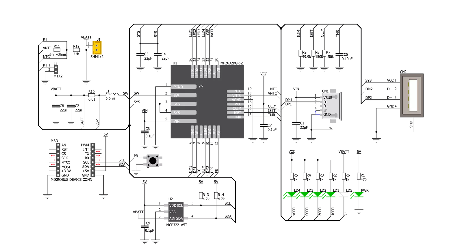
Click board™ Schematic
Step by step
Project assembly

Start by selecting your development board and Click board™. Begin with the EasyAVR v7 as your development board.


Software Support
Library Description
This library contains API for PowerBank Click driver.
Key functions:
uint16_t powerbank_read_data ( );- Function is used to read raw data from MCP3221.uint16_t powerbank_read_voltage ( uint16_t v_ref );- Function is used to calculate voltage of the connected battery.
Open Source
Code example
The complete application code and a ready-to-use project are available through the NECTO Studio Package Manager for direct installation in the NECTO Studio. The application code can also be found on the MIKROE GitHub account.
/*!
 * \file
 * \brief PowerBank Click example
 *
 * # Description
 * This application is example of the PowerBank Click functionality
 *
 * The demo application is composed of two sections :
 *
 * ## Application Init
 * Initalizes I2C driver and makes an initial log.
 *
 * ## Application Task
 * This example shows the capabilities of the
 * PowerBank Click by measuring voltage of the connected
 * battery. In order to get correct calculations user should
 * change "v_ref" value to his own power supply voltage.
 *
 *
 * \author MikroE Team
 *
 */
// ------------------------------------------------------------------- INCLUDES

#include "board.h"
#include "log.h"
#include "powerbank.h"

// ------------------------------------------------------------------ VARIABLES

static powerbank_t powerbank;
static log_t logger;

void application_init ( void )
{
    log_cfg_t log_cfg;
    powerbank_cfg_t cfg;

    /**
     * Logger initialization.
     * Default baud rate: 115200
     * Default log level: LOG_LEVEL_DEBUG
     * @note If USB_UART_RX and USB_UART_TX
     * are defined as HAL_PIN_NC, you will
     * need to define them manually for log to work.
     * See @b LOG_MAP_USB_UART macro definition for detailed explanation.
     */
    LOG_MAP_USB_UART( log_cfg );
    log_init( &logger, &log_cfg );
    log_info( &logger, "---- Application Init ----" );

    //  Click initialization.

    powerbank_cfg_setup( &cfg );
    POWERBANK_MAP_MIKROBUS( cfg, MIKROBUS_1 );
    powerbank_init( &powerbank, &cfg );

    Delay_ms ( 100 );
    log_printf( &logger, "------------------------\r\n" );
    log_printf( &logger, "     PowerBank Click    \r\n" );
    log_printf( &logger, "------------------------\r\n" );
}

void application_task ( void )
{
    uint16_t voltage;
    uint16_t v_ref = 5075;

    voltage = powerbank_read_voltage( &powerbank, v_ref );
    log_printf( &logger, "Battery voltage: %d mV\r\n", voltage );

    log_printf( &logger, "------------------------\r\n" );
    Delay_ms ( 1000 );
    Delay_ms ( 1000 );
}

int main ( void )
{
    /* Do not remove this line or clock might not be set correctly. */
    #ifdef PREINIT_SUPPORTED
    preinit();
    #endif

    application_init( );

    for ( ; ; )
    {
        application_task( );
    }

    return 0;
}
// ------------------------------------------------------------------------ END
Additional Support
Resources
Category:Battery charger


