Create a futuristic and user-friendly interface using IQS333 and PIC32MZ1024EFH064
Elegance in control

Published Aug 07, 2023
Click board™
Cap Wheel Click
Dev. board
PIC32MZ clicker
Compiler
NECTO Studio
MCU
PIC32MZ1024EFH064
Elevate your experience with our capacitive touch button that delivers precision and responsiveness, making every interaction a delightful journey
A
A
Hardware Overview
How does it work?
CAP Wheel Click is based on the IQS333, ProxSense® IC, a 9-channel projected (or 7-channel self) capacitive proximity, and a touch controller from Azoteq. This IC has advanced features such as auto drift compensation, Long proximity range, Automatic adjustment for optimal performance (ATI), two Configurable 11-bit sliders/scroll wheels, and more. These features enable CAP Wheel Click to exhibit reliable and accurate touch detection. Capacitive touch sensing is based on detecting a change in capacitance due to the influence of a foreign object. The capacitance of the sensor, also known as the antenna, is measured and monitored, and if a significant change occurs after processing by the detection integrator, a touch event is
acknowledged. Many routing requirements need to be met in the sensing electrode design to maximize performance. The relation between the sensing elements in position and size is crucial. CAP Wheel click is designed with these requirements, and electrodes are „Self-Capacitive Wheel“ shaped. CAP Wheel click also contains 8 LEDs whose function can be user-defined. LEDs are connected to PWM LED driver pins on IQS333, so the user can turn LEDs on or off and control illumination using the dimming modes that IQS333 supports. The IQS333 IC interfaces to a master controller via a 3-wire (SDA, SCL, and RDY) serial interface bus that is I2C™ compatible, with a maximum communication speed of 400kbit/s. The host MCU can force communication anytime by
pulling the RDY line low. The communication will start directly following the current conversion cycle. If the watchdog timer terminates the event, the device will reset. After every power-on cycle, the device will recalibrate itself. It will take some time, so it should be considered when building custom applications. MikroElektronika provides libraries and the demo application to be used as a reference for future designs. As mentioned, this Click board™ is I2C compatible and uses SCL, SDA, and RDY pins for communication routed to SCL, SDA, and INT pins on mikroBUS™, respectively. Besides that, a CLR pin is available on board which is routed to the RST pin on mikroBUS™ and used to master reset the IC.


Features overview
Development board
PIC32MZ Clicker is a compact starter development board that brings the flexibility of add-on Click boards™ to your favorite microcontroller, making it a perfect starter kit for implementing your ideas. It comes with an onboard 32-bit PIC32MZ microcontroller with FPU from Microchip, a USB connector, LED indicators, buttons, a mikroProg connector, and a header for interfacing with external electronics. Thanks to its compact design with clear and easy-recognizable silkscreen markings, it provides a fluid and immersive working experience, allowing access anywhere and under
any circumstances. Each part of the PIC32MZ Clicker development kit contains the components necessary for the most efficient operation of the same board. In addition to the possibility of choosing the PIC32MZ Clicker programming method, using USB HID mikroBootloader, or through an external mikroProg connector for PIC, dsPIC, or PIC32 programmer, the Clicker board also includes a clean and regulated power supply module for the development kit. The USB Micro-B connection can provide up to 500mA of current, which is more than enough to operate all onboard
and additional modules. All communication methods that mikroBUS™ itself supports are on this board, including the well-established mikroBUS™ socket, reset button, and several buttons and LED indicators. PIC32MZ Clicker is an integral part of the Mikroe ecosystem, allowing you to create a new application in minutes. Natively supported by Mikroe software tools, it covers many aspects of prototyping thanks to a considerable number of different Click boards™ (over a thousand boards), the number of which is growing every day.

Microcontroller Overview
MCU Card / MCU

Architecture
PIC32
MCU Memory (KB)
1024
Silicon Vendor
Microchip
Pin count
64
RAM (Bytes)
524288
Used MCU Pins
mikroBUS™ mapper
Take a closer look
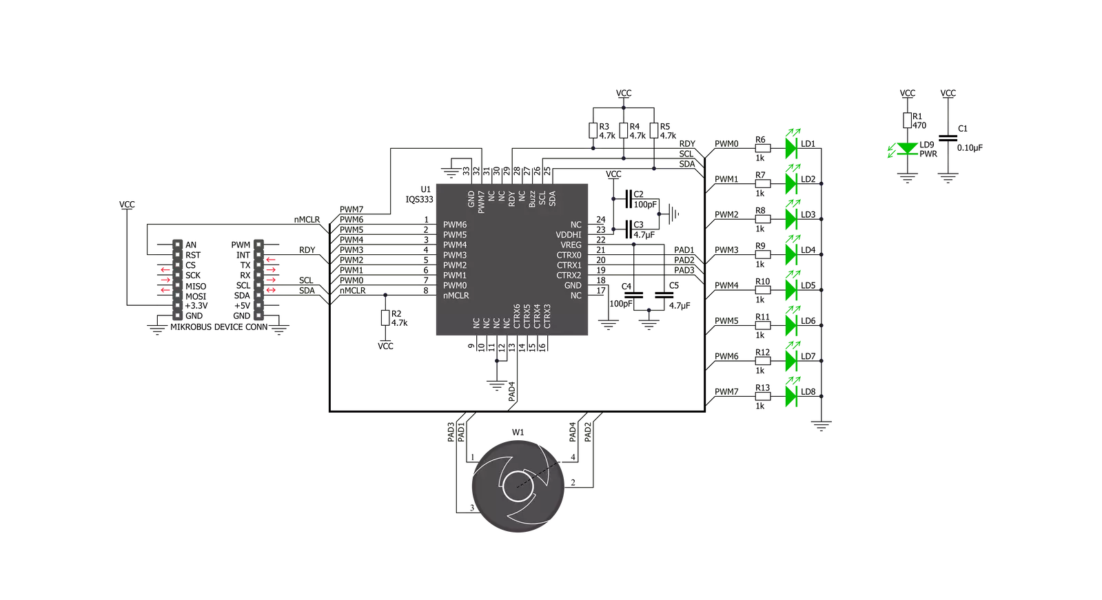
Click board™ Schematic
Step by step
Project assembly

Start by selecting your development board and Click board™. Begin with the PIC32MZ clicker as your development board.


Software Support
Library Description
This library contains API for CAP Wheel Click driver.
Key functions:
capwheel_write_reg- Generic Write functioncapwheel_read_reg- Generic Read functioncapwheel_check_data_ready- Data Ready Check function.
Open Source
Code example
The complete application code and a ready-to-use project are available through the NECTO Studio Package Manager for direct installation in the NECTO Studio. The application code can also be found on the MIKROE GitHub account.
/*!
 * \file
 * \brief CapWheel Click example
 *
 * # Description
 * This application is use for controling various devices.
 *
 * The demo application is composed of two sections :
 *
 * ## Application Init
 * Initializes I2C interface, performs the device reset and
 * activates the desired channels (from CH0 to CH9), in this example all channels are activated.
 *
 * ## Application Task
 * Checks is sense data ready for reading and if was ready,
  then reads wheel coordinates and sends these results to the LEDs.
 *
 * \author MikroE Team
 *
 */
// ------------------------------------------------------------------- INCLUDES

#include "board.h"
#include "log.h"
#include "capwheel.h"

// ------------------------------------------------------------------ VARIABLES

static capwheel_t capwheel;
static log_t logger;

void application_init ( void )
{
    log_cfg_t log_cfg;
    capwheel_cfg_t cfg;

    /**
     * Logger initialization.
     * Default baud rate: 115200
     * Default log level: LOG_LEVEL_DEBUG
     * @note If USB_UART_RX and USB_UART_TX
     * are defined as HAL_PIN_NC, you will
     * need to define them manually for log to work.
     * See @b LOG_MAP_USB_UART macro definition for detailed explanation.
     */
    LOG_MAP_USB_UART( log_cfg );
    log_init( &logger, &log_cfg );
    log_info( &logger, "---- Application Init ----" );

    //  Click initialization.

    capwheel_cfg_setup( &cfg );
    CAPWHEEL_MAP_MIKROBUS( cfg, MIKROBUS_1 );
    capwheel_init( &capwheel, &cfg );

    capwheel_reset ( &capwheel );
    capwheel_enable_chann( &capwheel, CAPWHEEL_CH0_PROX_EN | CAPWHEEL_CH1_EN | CAPWHEEL_CH2_EN |
                            CAPWHEEL_CH3_EN | CAPWHEEL_CH4_EN | CAPWHEEL_CH5_EN | CAPWHEEL_CH6_EN |
                            CAPWHEEL_CH7_EN | CAPWHEEL_CH8_EN | CAPWHEEL_CH9_EN );
    capwheel_set_threshold( &capwheel, 0x03 );
    Delay_ms ( 500 );

    log_printf( &logger, "CAP Wheel is initialized and ready\r\n" );
}

void application_task ( void )
{
    uint16_t sense_data;
    uint8_t ready_check;

    ready_check = capwheel_check_data_ready( &capwheel );

    if (ready_check == CAPWHEEL_DATA_READY)
    {
        capwheel_get_data( &capwheel, &sense_data );

        capwheel_set_output( &capwheel, sense_data, CAPWHEEL_LED_BRIGHTNESS_NUMBER );
    }
}

int main ( void )
{
    /* Do not remove this line or clock might not be set correctly. */
    #ifdef PREINIT_SUPPORTED
    preinit();
    #endif

    application_init( );

    for ( ; ; )
    {
        application_task( );
    }

    return 0;
}


// ------------------------------------------------------------------------ END


