Achieve automatic adjustment of lighting based on ambient light conditions using the ISL76682 and PIC32MX470F512H
Automotive high-sensitivity light-to-digital sensing solution
Published May 20, 2024
Click board™
Light 2 Click
Dev. board
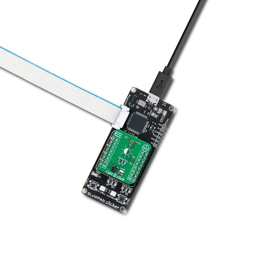
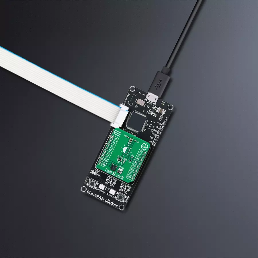
6LoWPAN clicker
Compiler
NECTO Studio
MCU
PIC32MX470F512H
Accurate light measurement capabilities for automotive, display backlighting control, industrial, and various scenarios requiring precise light sensing.
A
A
Hardware Overview
How does it work?
Light 2 Click is based on the ISL76682, an automotive low-power, high-sensitivity, light-to-digital sensor with an I2C interface from Renesas. Designed for precise light measurement, the ISL76682 features a state-of-the-art photodiode array that closely mimics the human eye's response while effectively rejecting UV and infrared light. It includes an ADC that eliminates flickers at 50Hz and 60Hz from artificial lighting. Users can adjust the light measurement range through the I2C interface, with four selectable ranges from as low as 0.015lux up to 64.000lux, enhancing the flexibility and accuracy of light intensity readings. It's ideally suited for automotive interior lighting
adjustment, display backlighting control, and light measurement in industrial and medical environments. The ISL76682 operates with low energy consumption, typically around 55µA in its Standard mode. It includes options for further reducing power usage through two power-down modes. The automatic power-down function turns off the sensor after each light measurement cycle when set to polling mode, while a software-controlled mode via the I2C interface can lower the power draw to less than 1µA. The ISL76682 outputs a simple code corresponding to the lux level, offers up to 16-bit resolution, and adapts to various lighting conditions, including direct sunlight.
Light 2 Click uses a standard 2-wire I2C interface to communicate with the host MCU, supporting Standard mode with up to 400kHz of frequency clock. In addition to I2C pins, the device allows the selection of I2C slave address between 0x44 and 0x45 via an SMD jumper marked as ADDR SEL. This Click board™ can be operated only with a 3.3V logic voltage level. The board must perform appropriate logic voltage level conversion before using MCUs with different logic levels. Also, it comes equipped with a library containing functions and an example code that can be used as a reference for further development.

Features overview
Development board
6LoWPAN Clicker is a compact starter development board that brings the flexibility of add-on Click boards™ to your favorite microcontroller, making it a perfect starter kit for implementing your ideas. It comes with an onboard 32-bit PIC microcontroller, the PIC32MX470F512H from Microchip, a USB connector, LED indicators, buttons, a mikroProg connector, and a header for interfacing with external electronics. Along with this microcontroller, the board also contains a 2.4GHz ISM band transceiver, allowing you to add wireless communication to your target application. Its compact design provides a fluid and immersive working experience, allowing access anywhere
and under any circumstances. Each part of the 6LoWPAN Clicker development kit contains the components necessary for the most efficient operation of the same board. In addition to the possibility of choosing the 6LoWPAN Clicker programming method, using USB HID mikroBootloader, or through an external mikroProg connector for PIC, dsPIC, or PIC32 programmer, the Clicker board also includes a clean and regulated power supply module for the development kit. The USB Micro-B connection can provide up to 500mA of current for the Clicker board, which is more than enough to operate all onboard and additional modules, or it can power
over two standard AA batteries. All communication methods that mikroBUS™ itself supports are on this board, including the well-established mikroBUS™ socket, reset button, and several buttons and LED indicators. 6LoWPAN Clicker is an integral part of the Mikroe ecosystem, allowing you to create a new application in minutes. Natively supported by Mikroe software tools, it covers many aspects of prototyping thanks to a considerable number of different Click boards™ (over a thousand boards), the number of which is growing every day.

Microcontroller Overview
MCU Card / MCU

Architecture
PIC32
MCU Memory (KB)
512
Silicon Vendor
Microchip
Pin count
64
RAM (Bytes)
131072
Used MCU Pins
mikroBUS™ mapper
Take a closer look
Click board™ Schematic

Step by step
Project assembly

Start by selecting your development board and Click board™. Begin with the 6LoWPAN clicker as your development board.


Track your results in real time
Application Output
1. Application Output - In Debug mode, the 'Application Output' window enables real-time data monitoring, offering direct insight into execution results. Ensure proper data display by configuring the environment correctly using the provided tutorial.

2. UART Terminal - Use the UART Terminal to monitor data transmission via a USB to UART converter, allowing direct communication between the Click board™ and your development system. Configure the baud rate and other serial settings according to your project's requirements to ensure proper functionality. For step-by-step setup instructions, refer to the provided tutorial.

3. Plot Output - The Plot feature offers a powerful way to visualize real-time sensor data, enabling trend analysis, debugging, and comparison of multiple data points. To set it up correctly, follow the provided tutorial, which includes a step-by-step example of using the Plot feature to display Click board™ readings. To use the Plot feature in your code, use the function: plot(*insert_graph_name*, variable_name);. This is a general format, and it is up to the user to replace 'insert_graph_name' with the actual graph name and 'variable_name' with the parameter to be displayed.

Software Support
Library Description
This library contains API for Light 2 Click driver.
Key functions:
light2_read_raw_data- This function reads raw data from the ADC of Light 2 click board.light2_get_cal_const- This function is used to get a calculation constant depending on Light 2 click board configuration.light2_get_light_data- This function is used to read light data of Light 2 click board configuration.
Open Source
Code example
The complete application code and a ready-to-use project are available through the NECTO Studio Package Manager for direct installation in the NECTO Studio. The application code can also be found on the MIKROE GitHub account.
/*!
 * @file main.c
 * @brief Light 2 Click example
 *
 * # Description
 * This example demonstrates the use of Light 2 Click board by measuring
 * the ambient light level in Lux.
 *
 * The demo application is composed of two sections :
 *
 * ## Application Init
 * Initializes the driver and performs the Click default configuration.
 *
 * ## Application Task
 * Reads the ADC voltage and then calculates the illuminance from it.
 * The calculated value of illuminance in lux is being displayed on the USB UART approximately once per second.
 *
 * @author Stefan Ilic
 *
 */

#include "board.h"
#include "log.h"
#include "light2.h"

static light2_t light2;
static log_t logger;

void application_init ( void )
{
    log_cfg_t log_cfg;  /**< Logger config object. */
    light2_cfg_t light2_cfg;  /**< Click config object. */

    /**
     * Logger initialization.
     * Default baud rate: 115200
     * Default log level: LOG_LEVEL_DEBUG
     * @note If USB_UART_RX and USB_UART_TX
     * are defined as HAL_PIN_NC, you will
     * need to define them manually for log to work.
     * See @b LOG_MAP_USB_UART macro definition for detailed explanation.
     */
    LOG_MAP_USB_UART( log_cfg );
    log_init( &logger, &log_cfg );
    log_info( &logger, " Application Init " );

    // Click initialization.
    light2_cfg_setup( &light2_cfg );
    LIGHT2_MAP_MIKROBUS( light2_cfg, MIKROBUS_1 );
    if ( I2C_MASTER_ERROR == light2_init( &light2, &light2_cfg ) )
    {
        log_error( &logger, " Communication init." );
        for ( ; ; );
    }

    if ( LIGHT2_ERROR == light2_default_cfg ( &light2 ) )
    {
        log_error( &logger, " Default configuration." );
        for ( ; ; );
    }

    log_info( &logger, " Application Task " );
}

void application_task ( void )
{
    float lux_data = 0;

    light2_get_light_data( &light2, &lux_data );
    log_printf( &logger, " LUX data: %.2f LUX \r\n", lux_data );

    Delay_ms ( 1000 );
}

int main ( void )
{
    /* Do not remove this line or clock might not be set correctly. */
    #ifdef PREINIT_SUPPORTED
    preinit();
    #endif

    application_init( );

    for ( ; ; )
    {
        application_task( );
    }

    return 0;
}

// ------------------------------------------------------------------------ END


