Embark on a journey of motion mastery with ISM330IS and PIC32MZ1024EFH064
Open the door to limitless possibilities in motion sensing and processing

Published Nov 12, 2023
Click board™
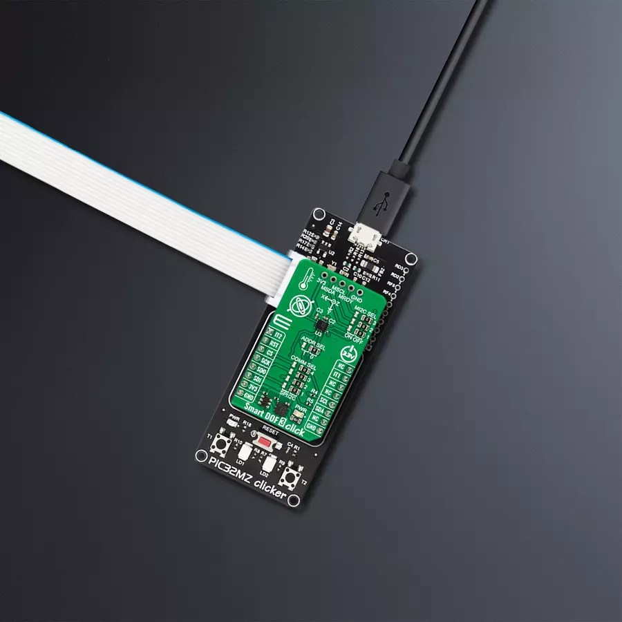
Smart DOF 3 Click
Dev. board
PIC32MZ clicker
Compiler
NECTO Studio
MCU
PIC32MZ1024EFH064
Revolutionize motion insights with our cutting-edge solution, blending the always-on 3-axis accelerometer and 3-axis gyroscope. This dynamic duo, enhanced by Intelligent Sensor Processing, delivers unparalleled accuracy, enabling a seamless understanding of movement for diverse applications.
A
A
Hardware Overview
How does it work?
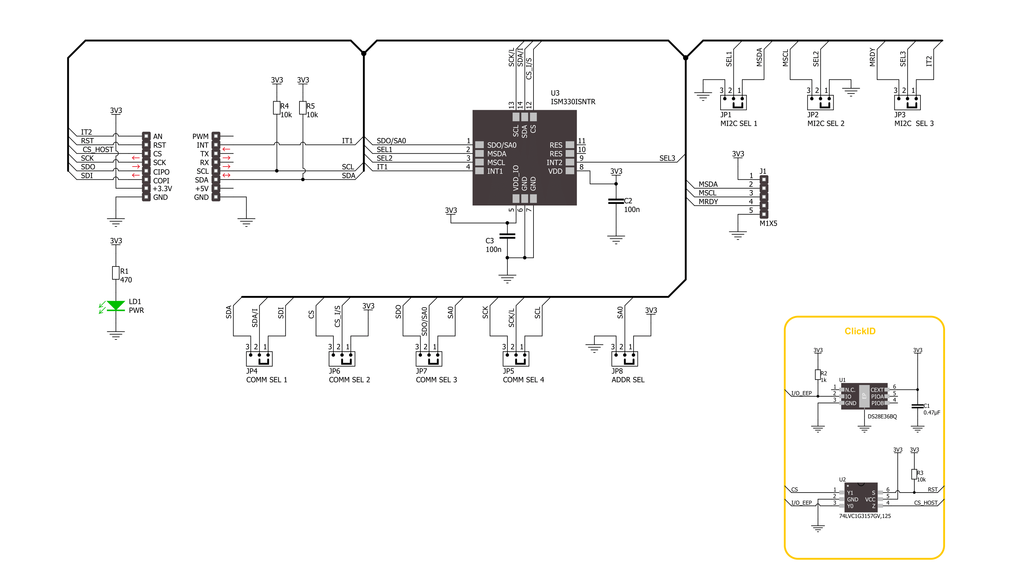
Smart DOF 3 Click is based on the ISM330IS, an iNEMO inertial module from STMicroelectronics. There are three modes of operation in which both the accelerometer and gyroscope can be turned on/off independently of each other and are allowed to have different ODRs and power modes. It has a full-scale 3-axis selectable acceleration in a range of ±2/±4/±8/±16g. There are also self-test modes, both angular and linear, for acceleration. The 3-axis gyroscope comes in a selectable full-scale rate range of ±125/±250/±500/±1000/±2000dps. In addition to those two sensors, the third one is an embedded temperature sensor, whose values are used for calibration purposes. The ISPU core executes signal processing and AI algorithms on edge, and its main benefits are C programming and an enhanced ecosystem with libraries and third-party tools/IDE. The ISPU has 32KB of program RAM, 8KB of data RAM, and an FPU supporting addition, subtraction, and multiplication. It also features programmable interrupts and an embedded
sensor hub, which, besides an accelerometer and gyroscope, includes four more external sensors that can be connected directly to the ISM330IS and its internal master I2C lines. This I2C interface can connect over the 5-pin top header, which includes master SDA, SCL, and Ready pins (MSDA, MSCL, MRDY). To use this I2C interface, you must set all three MI2C SEL jumpers in the ON position (OFF set by default). Smart DOF 3 Click can communicate with the host MCU by selecting one between the I2C and SPI interfaces over the COMM SEL jumper, where the I2C is selected by default. All four jumpers must be set into the appropriate position for this Click board™ to work properly. The standard 2-Wire I2C interface supports fast mode (400KHz) and fast mode plus (1MHz) clock frequencies. The I2C address can be selected over the ADDR SEL jumper, where 0 is set by default. If your choice is the SPI, this Click board™ supports both 3- and 4-Wire SPI serial interfaces with clock frequencies up to 100MHz. This Click board™ can be reset over the RST pin.
There are also two programmable interrupt pins, IT1 and IT2. The IT2 is a shared pin with the master I2C interface, so this interrupt pin will not be available if you use an external sensor. You can assign one of the interrupts to a different sensor so you know which sensor detected the movement. Depending on the usage of the ISM330IS, there are two mode connections. Both Mode 1 and Mode 2 can work in all supported types of communication between the IC and the host MCU. Mode 1 is when only this IC and the host MCU are in a communication connection. Mode 2 is the scene where, in addition to the Mode 1 connection, there are external sensors connected over the master I2C to the ISM330IS. This Click board™ can be operated only with a 3.3V logic voltage level. The board must perform appropriate logic voltage level conversion before using MCUs with different logic levels. Also, it comes equipped with a library containing functions and an example code that can be used as a reference for further development.

Features overview
Development board
PIC32MZ Clicker is a compact starter development board that brings the flexibility of add-on Click boards™ to your favorite microcontroller, making it a perfect starter kit for implementing your ideas. It comes with an onboard 32-bit PIC32MZ microcontroller with FPU from Microchip, a USB connector, LED indicators, buttons, a mikroProg connector, and a header for interfacing with external electronics. Thanks to its compact design with clear and easy-recognizable silkscreen markings, it provides a fluid and immersive working experience, allowing access anywhere and under
any circumstances. Each part of the PIC32MZ Clicker development kit contains the components necessary for the most efficient operation of the same board. In addition to the possibility of choosing the PIC32MZ Clicker programming method, using USB HID mikroBootloader, or through an external mikroProg connector for PIC, dsPIC, or PIC32 programmer, the Clicker board also includes a clean and regulated power supply module for the development kit. The USB Micro-B connection can provide up to 500mA of current, which is more than enough to operate all onboard
and additional modules. All communication methods that mikroBUS™ itself supports are on this board, including the well-established mikroBUS™ socket, reset button, and several buttons and LED indicators. PIC32MZ Clicker is an integral part of the Mikroe ecosystem, allowing you to create a new application in minutes. Natively supported by Mikroe software tools, it covers many aspects of prototyping thanks to a considerable number of different Click boards™ (over a thousand boards), the number of which is growing every day.

Microcontroller Overview
MCU Card / MCU

Architecture
PIC32
MCU Memory (KB)
1024
Silicon Vendor
Microchip
Pin count
64
RAM (Bytes)
524288
Used MCU Pins
mikroBUS™ mapper
Take a closer look
Click board™ Schematic
Step by step
Project assembly

Start by selecting your development board and Click board™. Begin with the PIC32MZ clicker as your development board.


Software Support
Library Description
This library contains API for Smart DOF 3 Click driver.
Key functions:
smartdof3_get_acc_axis- Smart DOF 3 get the accel sensor axes function.smartdof3_get_gyro_axis- Smart DOF 3 get the gyro sensor axes function.smartdof3_get_temperature- Smart DOF 3 get the temperature function.
Open Source
Code example
The complete application code and a ready-to-use project are available through the NECTO Studio Package Manager for direct installation in the NECTO Studio. The application code can also be found on the MIKROE GitHub account.
/*!
 * @file main.c
 * @brief Smart DOF 3 Click example
 *
 * # Description
 * This library contains API for Smart DOF 3 Click driver.
 * The library initializes and defines the I2C and SPI bus drivers to
 * write and read data from registers, as well as the default
 * configuration for reading accelerator and gyroscope data.
 *
 * The demo application is composed of two sections :
 *
 * ## Application Init
 * The initialization of I2C or SPI module, log UART, and additional pins.
 * After the driver init, the app executes a default configuration.
 *
 * ## Application Task
 * This example demonstrates the use of the Smart DOF 3 Click board™.
 * Measures and displays acceleration and gyroscope data for X-axis, Y-axis, and Z-axis.
 * Results are being sent to the UART Terminal, where you can track their changes.
 *
 * @author Nenad Filipovic
 *
 */

#include "board.h"
#include "log.h"
#include "smartdof3.h"

static smartdof3_t smartdof3;
static log_t logger;

void application_init ( void )
{
    log_cfg_t log_cfg;  /**< Logger config object. */
    smartdof3_cfg_t smartdof3_cfg;  /**< Click config object. */

    /**
     * Logger initialization.
     * Default baud rate: 115200
     * Default log level: LOG_LEVEL_DEBUG
     * @note If USB_UART_RX and USB_UART_TX
     * are defined as HAL_PIN_NC, you will
     * need to define them manually for log to work.
     * See @b LOG_MAP_USB_UART macro definition for detailed explanation.
     */
    LOG_MAP_USB_UART( log_cfg );
    log_init( &logger, &log_cfg );
    log_info( &logger, " Application Init " );

    // Click initialization.
    smartdof3_cfg_setup( &smartdof3_cfg );
    SMARTDOF3_MAP_MIKROBUS( smartdof3_cfg, MIKROBUS_1 );
    err_t init_flag = smartdof3_init( &smartdof3, &smartdof3_cfg );
    if ( ( I2C_MASTER_ERROR == init_flag ) || ( SPI_MASTER_ERROR == init_flag ) )
    {
        log_error( &logger, " Communication init." );
        for ( ; ; );
    }

    if ( SMARTDOF3_ERROR == smartdof3_default_cfg ( &smartdof3 ) )
    {
        log_error( &logger, " Default configuration." );
        for ( ; ; );
    }

    log_info( &logger, " Application Task " );
    log_printf( &logger, "--------------------------------------\r\n" );
    Delay_ms ( 100 );
}

void application_task ( void )
{
    static smartdof3_axis_t acc_axis, gyro_axis;
    if ( ( SMARTDOF3_OK == smartdof3_get_acc_axis( &smartdof3, &acc_axis ) ) &&
         ( SMARTDOF3_OK == smartdof3_get_gyro_axis( &smartdof3, &gyro_axis ) ) )
    {
        log_printf( &logger, " Accel X: %.2f mg | Gyro X: %.2f dps\r\n", acc_axis.x, gyro_axis.x );
        log_printf( &logger, " Accel Y: %.2f mg | Gyro Y: %.2f dps\r\n", acc_axis.y, gyro_axis.y );
        log_printf( &logger, " Accel Z: %.2f mg | Gyro Z: %.2f dps\r\n", acc_axis.z, gyro_axis.z );
        log_printf( &logger, "--------------------------------------\r\n" );
    }
    Delay_ms ( 1000 );
}

int main ( void )
{
    /* Do not remove this line or clock might not be set correctly. */
    #ifdef PREINIT_SUPPORTED
    preinit();
    #endif

    application_init( );

    for ( ; ; )
    {
        application_task( );
    }

    return 0;
}

// ------------------------------------------------------------------------ END


