Prosper in robotics, industrial automation, or vibration monitoring thanks to the ICM-42688-P and MK64FN1M0VDC12
Precision in every move: Where innovation meets 6DoF technology

Published Oct 08, 2023
Click board™
6DOF IMU 14 Click
Dev. board
Clicker 2 for Kinetis
Compiler
NECTO Studio
MCU
MK64FN1M0VDC12
Experience a new level of immersion with our 6-axis motion tracking solution, which is engineered to deliver the most authentic and realistic experiences across various industries
A
A
Hardware Overview
How does it work?
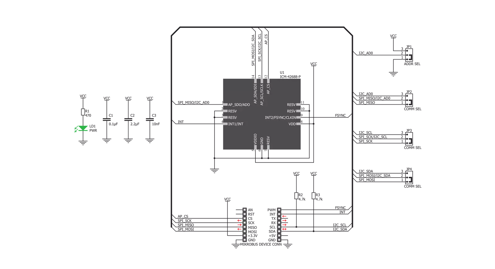
6DOF IMU 14 Click is based on the ICM-42688-P, high precision 6-axis MEMS motion tracking device from TDK InvenSense. It features a 2kB FIFO that can lower the traffic on the serial bus interface, and reduce power consumption by allowing the system processor to burst read sensor data, and then go into a low-power mode. It also supports external clock input for highly accurate 31kHz to 50kHz clock, which helps to reduce system-level sensitivity error and improve orientation measurement from gyroscope data. ICM-42688-P includes an industry-first 20-bits data format support in FIFO for high-data resolution. This FIFO format encapsulates 19-bits of gyroscope data and 18-bits of accelerometer data. This Click board™ includes a vibratory MEMS rate gyroscope that detects rotation about the X-, Y-, and Z- axes, and a 3-axis MEMS accelerometer. The full-scale range of the gyro sensors may be
digitally programmed from ±15.625 up to ±2000 degrees per second (DPS). The ICM-42688-P architecture reduces the accelerometer's sensitivity to fabrication variations as well as to thermal drift. When the device is placed on a flat surface, it will measure 0g on the X- and Y-axes and +1g on the Z-axis. The full-scale range of the digital output can be adjusted from ±2g, up to ±16g. The ICM-42688-P has a programmable interrupt system that can generate an interrupt signal. There are two interrupt outputs in which one of them represents frame synchronization input routed to the PWM pins on the mikroBUS™. An interrupt can be triggered while switching clock sources, when new data is available for reading (from the FIFO and data registers), during accelerometer events, FIFO watermark and overflow. 6DOF IMU 14 Click provides the possibility of using both I2C and SPI interfaces
with a maximum frequency of 1MHz for I2C and 25MHz for SPI communication. The selection can be done by positioning SMD jumpers labeled as COMM SEL to an appropriate position. Note that all the jumpers must be placed to the same side, or else the Click board™ may become unresponsive. While the I2C interface is selected, the ICM-42688-P allows the choice of the least significant bit (LSB) of its I2C slave address. This can be done by using the SMD jumper labeled as ADDR SEL. This Click board™ can be operated only with a 3.3V logic voltage level. The board must perform appropriate logic voltage level conversion before using MCUs with different logic levels. Also, it comes equipped with a library containing functions and an example code that can be used as a reference for further development.


Features overview
Development board
Clicker 2 for Kinetis is a compact starter development board that brings the flexibility of add-on Click boards™ to your favorite microcontroller, making it a perfect starter kit for implementing your ideas. It comes with an onboard 32-bit ARM Cortex-M4F microcontroller, the MK64FN1M0VDC12 from NXP Semiconductors, two mikroBUS™ sockets for Click board™ connectivity, a USB connector, LED indicators, buttons, a JTAG programmer connector, and two 26-pin headers for interfacing with external electronics. Its compact design with clear and easily recognizable silkscreen markings allows you to build gadgets with unique functionalities and
features quickly. Each part of the Clicker 2 for Kinetis development kit contains the components necessary for the most efficient operation of the same board. In addition to the possibility of choosing the Clicker 2 for Kinetis programming method, using a USB HID mikroBootloader or an external mikroProg connector for Kinetis programmer, the Clicker 2 board also includes a clean and regulated power supply module for the development kit. It provides two ways of board-powering; through the USB Micro-B cable, where onboard voltage regulators provide the appropriate voltage levels to each component on the board, or
using a Li-Polymer battery via an onboard battery connector. All communication methods that mikroBUS™ itself supports are on this board, including the well-established mikroBUS™ socket, reset button, and several user-configurable buttons and LED indicators. Clicker 2 for Kinetis is an integral part of the Mikroe ecosystem, allowing you to create a new application in minutes. Natively supported by Mikroe software tools, it covers many aspects of prototyping thanks to a considerable number of different Click boards™ (over a thousand boards), the number of which is growing every day.

Microcontroller Overview
MCU Card / MCU

Architecture
ARM Cortex-M4
MCU Memory (KB)
1024
Silicon Vendor
NXP
Pin count
121
RAM (Bytes)
262144
Used MCU Pins
mikroBUS™ mapper
Take a closer look
Click board™ Schematic
Step by step
Project assembly

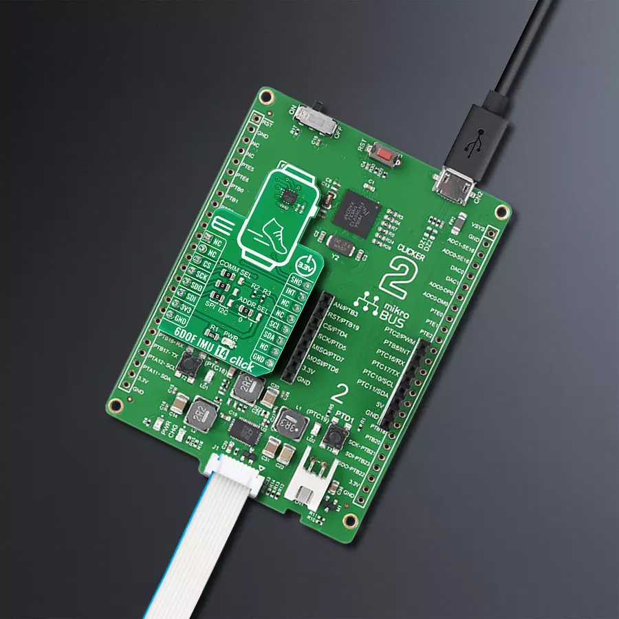
Start by selecting your development board and Click board™. Begin with the Clicker 2 for Kinetis as your development board.


Software Support
Library Description
This library contains API for 6DOF IMU 14 Click driver.
Key functions:
c6dofimu14_get_data- This function reads accel and gyro data for all three axisc6dofimu14_get_temperature- This function reads the raw temperature data and converts it to Celsiusc6dofimu14_software_reset- This function performs the device software reset
Open Source
Code example
The complete application code and a ready-to-use project are available through the NECTO Studio Package Manager for direct installation in the NECTO Studio. The application code can also be found on the MIKROE GitHub account.
/*!
 * @file main.c
 * @brief 6DOFIMU14 Click example
 *
 * # Description
 * This example demonstrates the use of 6DOF IMU 14 Click board.
 *
 * The demo application is composed of two sections :
 *
 * ## Application Init
 * Initializes the driver and configures the Click board.
 *
 * ## Application Task
 * Reads accel, gyro, and temperature data and displays the results
 * on the USB UART approximately every 500ms.
 *
 * @note
 * In the case of I2C, the example doesn't work properly on some of the 8-bit PICs (ex. PIC18F97J94).
 *
 * @author Stefan Filipovic
 *
 */

#include "board.h"
#include "log.h"
#include "c6dofimu14.h"

static c6dofimu14_t c6dofimu14;
static log_t logger;

void application_init ( void )
{
    log_cfg_t log_cfg;  /**< Logger config object. */
    c6dofimu14_cfg_t c6dofimu14_cfg;  /**< Click config object. */

    /**
     * Logger initialization.
     * Default baud rate: 115200
     * Default log level: LOG_LEVEL_DEBUG
     * @note If USB_UART_RX and USB_UART_TX
     * are defined as HAL_PIN_NC, you will
     * need to define them manually for log to work.
     * See @b LOG_MAP_USB_UART macro definition for detailed explanation.
     */
    LOG_MAP_USB_UART( log_cfg );
    log_init( &logger, &log_cfg );
    Delay_ms ( 100 );
    log_info( &logger, " Application Init " );

    // Click initialization.

    c6dofimu14_cfg_setup( &c6dofimu14_cfg );
    C6DOFIMU14_MAP_MIKROBUS( c6dofimu14_cfg, MIKROBUS_1 );
    err_t init_flag = c6dofimu14_init( &c6dofimu14, &c6dofimu14_cfg );
    if ( ( init_flag == I2C_MASTER_ERROR ) || ( init_flag == SPI_MASTER_ERROR ) )
    {
        log_error( &logger, " Application Init Error. " );
        log_info( &logger, " Please, run program again... " );

        for ( ; ; );
    }
    Delay_ms ( 100 );

    if ( c6dofimu14_default_cfg ( &c6dofimu14 ) != C6DOFIMU14_OK )
    {
        log_error( &logger, " Default Config Error. " );
        log_info( &logger, " Please, run program again... " );

        for ( ; ; );
    }
    Delay_ms ( 100 );

    log_info( &logger, " Application Task " );
}

void application_task ( void )
{
    float temperature;
    c6dofimu14_axis_t accel;
    c6dofimu14_axis_t gyro;

    c6dofimu14_get_data( &c6dofimu14, &accel, &gyro );
    c6dofimu14_get_temperature( &c6dofimu14, &temperature );

    log_printf( &logger, " Accel X: %d | Gyro X: %d\r\n", accel.x, gyro.x );
    log_printf( &logger, " Accel Y: %d | Gyro Y: %d\r\n", accel.y, gyro.y );
    log_printf( &logger, " Accel Z: %d | Gyro Z: %d\r\n", accel.z, gyro.z );
    log_printf( &logger, " Temperature: %.2f C\r\n", temperature );
    log_printf( &logger, "----------------------------------\r\n");

    Delay_ms ( 500 );
}

int main ( void )
{
    /* Do not remove this line or clock might not be set correctly. */
    #ifdef PREINIT_SUPPORTED
    preinit();
    #endif

    application_init( );

    for ( ; ; )
    {
        application_task( );
    }

    return 0;
}

// ------------------------------------------------------------------------ END
Additional Support
Resources
Category:Motion


