Create interactive applications that respond to physical movements with RB44145 and STM32L073RZ
Switch to safety: When tilt's just too much!

Published Feb 26, 2024
Click board™
Tilt 2 Click
Dev. board
Nucleo-64 with STM32L073RZ MCU
Compiler
NECTO Studio
MCU
STM32L073RZ
With our state-of-the-art tilt sensor switch, you can effortlessly monitor and respond to changes in orientation, enabling a wide range of intelligent and automated systems
A
A
Hardware Overview
How does it work?
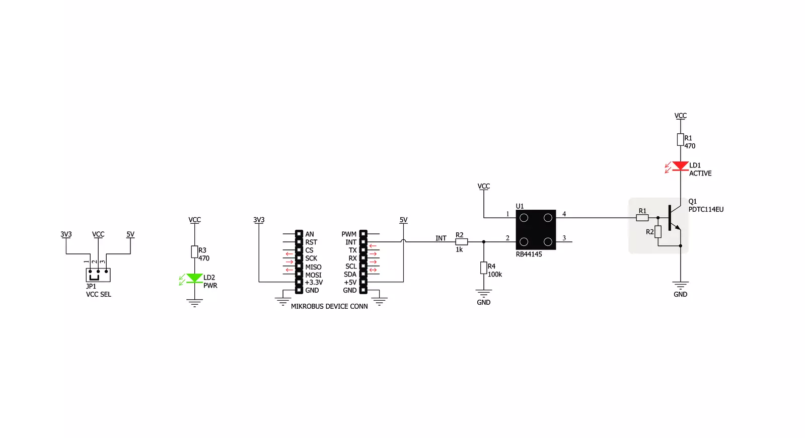
Tilt 2 Click is based on the RB44145, a 45° rolling ball sensor switch from C&K Switches, a factory specialized in the production of various kinds of switches. The RB-441-45 sensor does not use any mercury. It has a gold-plated ball in a PBT plastic enclosure. The PBT plastic enclosure ensures a high electrical insulation, while the gold plating ensures a low ON resistance. However, the sensor is not intended to be operated on high voltages. It should not be operated at more than 24V, while only a low signal-level current up to 25mA is allowed to flow through its contacts. The working principle of the RB-441-45 sensor switch with the rolling ball is simple. While it stands still, perpendicular to the ground surface, a small gold-plated rolling ball will be in contact with all four gold-plated terminals. As the ball moves, it will break the contacts. This is guaranteed to happen when the enclosure is tilted by 45° (±15°). Both the ball and the contacts are gold-plated for several reasons: the ball will not stick to the contacts, the contact resistance will be minimized, and there will be no corrosion of the outer layer, ensuring
the long life-cycle. The endurance of the tilt switch is specified to 100,000 cycles. The maximum voltage across the terminals should not exceed 24VDC, while the current should stay below 25mA. This prevents forming of micro-arcs that could cause surface damage and shorten the life-cycle of the sensor switch. Besides the tilt, the RB-441-45 sensor switch is also able to detect shaking, since any displacement of the ball will break the circuit. This extends its usability to various applications where a sudden movement might occur, such when hitting or punching something. By being able to sense even this type of movements, the switch can be used in various public entertainment machines (slot, pinball, videogame consoles…). Besides the RB-441-45 sensor switch, Tilt 2 click features a LED, which is driven via the NPN transistor: when the tilt sensor switch is closed, the transistor will be in a conductive state, and LED labeled as ACTIVE will be turned ON. When the switch contacts are broken (when tilted more than 45° or while being shaken), the ACTIVE LED will be turned OFF.
The VCC voltage is brought to the PIN 1. The VCC voltage can be selected by an SMD Jumper labeled as VCC SEL. It can be used to select either 3.3V or 5V from the mikroBUS™ power rails. Besides the LED, the INT pin from the mikroBUS™ is also connected to the sensor switch, allowing the host MCU to read the state of this switch. This pin is pulled to a LOW logic level by a resistor, so when deactivated, it will not float, but pulled to a LOW Logic level instead. When Activated, this pin will be set to a HIGH logic level, determined by a VCC SEL jumper. This allows the Click board™ to be used with both 3.3V and 5V MCUs. To ensure a reliable detection and bounce-free operation, the user should utilize the debouncing routines in the software. Due to the nature of the sensor switch, the software debouncing is a better solution in this case. Unlike the hardware solution, the software debouncing allows selecting the debouncing time, according to the specific application.


Features overview
Development board
Nucleo-64 with STM32L073RZ MCU offers a cost-effective and adaptable platform for developers to explore new ideas and prototype their designs. This board harnesses the versatility of the STM32 microcontroller, enabling users to select the optimal balance of performance and power consumption for their projects. It accommodates the STM32 microcontroller in the LQFP64 package and includes essential components such as a user LED, which doubles as an ARDUINO® signal, alongside user and reset push-buttons, and a 32.768kHz crystal oscillator for precise timing operations. Designed with expansion and flexibility in mind, the Nucleo-64 board features an ARDUINO® Uno V3 expansion connector and ST morpho extension pin
headers, granting complete access to the STM32's I/Os for comprehensive project integration. Power supply options are adaptable, supporting ST-LINK USB VBUS or external power sources, ensuring adaptability in various development environments. The board also has an on-board ST-LINK debugger/programmer with USB re-enumeration capability, simplifying the programming and debugging process. Moreover, the board is designed to simplify advanced development with its external SMPS for efficient Vcore logic supply, support for USB Device full speed or USB SNK/UFP full speed, and built-in cryptographic features, enhancing both the power efficiency and security of projects. Additional connectivity is
provided through dedicated connectors for external SMPS experimentation, a USB connector for the ST-LINK, and a MIPI® debug connector, expanding the possibilities for hardware interfacing and experimentation. Developers will find extensive support through comprehensive free software libraries and examples, courtesy of the STM32Cube MCU Package. This, combined with compatibility with a wide array of Integrated Development Environments (IDEs), including IAR Embedded Workbench®, MDK-ARM, and STM32CubeIDE, ensures a smooth and efficient development experience, allowing users to fully leverage the capabilities of the Nucleo-64 board in their projects.

Microcontroller Overview
MCU Card / MCU

Architecture
ARM Cortex-M0
MCU Memory (KB)
192
Silicon Vendor
STMicroelectronics
Pin count
64
RAM (Bytes)
20480
You complete me!
Accessories
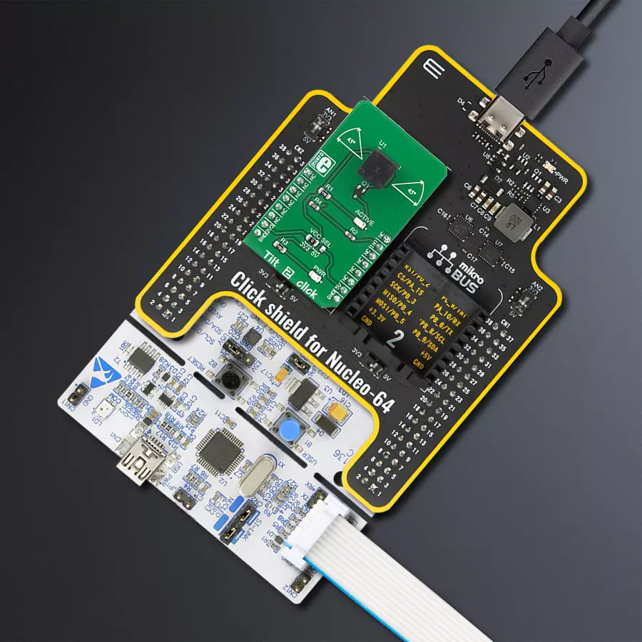
Click Shield for Nucleo-64 comes equipped with two proprietary mikroBUS™ sockets, allowing all the Click board™ devices to be interfaced with the STM32 Nucleo-64 board with no effort. This way, Mikroe allows its users to add any functionality from our ever-growing range of Click boards™, such as WiFi, GSM, GPS, Bluetooth, ZigBee, environmental sensors, LEDs, speech recognition, motor control, movement sensors, and many more. More than 1537 Click boards™, which can be stacked and integrated, are at your disposal. The STM32 Nucleo-64 boards are based on the microcontrollers in 64-pin packages, a 32-bit MCU with an ARM Cortex M4 processor operating at 84MHz, 512Kb Flash, and 96KB SRAM, divided into two regions where the top section represents the ST-Link/V2 debugger and programmer while the bottom section of the board is an actual development board. These boards are controlled and powered conveniently through a USB connection to program and efficiently debug the Nucleo-64 board out of the box, with an additional USB cable connected to the USB mini port on the board. Most of the STM32 microcontroller pins are brought to the IO pins on the left and right edge of the board, which are then connected to two existing mikroBUS™ sockets. This Click Shield also has several switches that perform functions such as selecting the logic levels of analog signals on mikroBUS™ sockets and selecting logic voltage levels of the mikroBUS™ sockets themselves. Besides, the user is offered the possibility of using any Click board™ with the help of existing bidirectional level-shifting voltage translators, regardless of whether the Click board™ operates at a 3.3V or 5V logic voltage level. Once you connect the STM32 Nucleo-64 board with our Click Shield for Nucleo-64, you can access hundreds of Click boards™, working with 3.3V or 5V logic voltage levels.

Used MCU Pins
mikroBUS™ mapper
Take a closer look
Click board™ Schematic
Step by step
Project assembly
Start by selecting your development board and Click board™. Begin with the Nucleo-64 with STM32L073RZ MCU as your development board.


Software Support
Library Description
This library contains API for Tilt 2 Click driver.
Key functions:
tilt2_tilt_detection- This function detection tilt
Open Source
Code example
The complete application code and a ready-to-use project are available through the NECTO Studio Package Manager for direct installation in the NECTO Studio. The application code can also be found on the MIKROE GitHub account.
/*!
 * \file
 * \brief Tilt 2 Click example
 *
 * # Description
 * This app detection tilt.
 *
 * The demo application is composed of two sections :
 *
 * ## Application Init
 * Initialization device.
 *
 * ## Application Task
 * Tilt detection, if the tilt is detected, the message is logs on USBUART.
 *
 * \author MikroE Team
 *
 */
// ------------------------------------------------------------------- INCLUDES

#include "board.h"
#include "log.h"
#include "tilt2.h"

// ------------------------------------------------------------------ VARIABLES

static tilt2_t tilt2;
static log_t logger;

// ------------------------------------------------------ APPLICATION FUNCTIONS

void application_init ( void )
{
    log_cfg_t log_cfg;
    tilt2_cfg_t cfg;

    /**
     * Logger initialization.
     * Default baud rate: 115200
     * Default log level: LOG_LEVEL_DEBUG
     * @note If USB_UART_RX and USB_UART_TX
     * are defined as HAL_PIN_NC, you will
     * need to define them manually for log to work.
     * See @b LOG_MAP_USB_UART macro definition for detailed explanation.
     */
    LOG_MAP_USB_UART( log_cfg );
    log_init( &logger, &log_cfg );
    log_info(&logger, "---- Application Init ----\r\n");

    //  Click initialization.

    tilt2_cfg_setup( &cfg );
    TILT2_MAP_MIKROBUS( cfg, MIKROBUS_1 );
    tilt2_init( &tilt2, &cfg );
}

void application_task ( void )
{
    uint8_t tilt;

    tilt = tilt2_tilt_detection( &tilt2 );
    if ( tilt == TILT2_TILT_DETECTION )
    {
        log_printf( &logger, " Tilt detection.. \r\n" );
        Delay_ms ( 300 );
    }
}

int main ( void )
{
    /* Do not remove this line or clock might not be set correctly. */
    #ifdef PREINIT_SUPPORTED
    preinit();
    #endif

    application_init( );

    for ( ; ; )
    {
        application_task( );
    }

    return 0;
}

// ------------------------------------------------------------------------ END
Additional Support
Resources
Category:Motion


