Design a convenient and portable charging solution with RT9480 and PIC32MZ1024EFH064
Recharge on the fly
Published Jun 02, 2023
Click board™
PowerBank 2 Click
Dev. board
PIC32MZ clicker
Compiler
NECTO Studio
MCU
PIC32MZ1024EFH064
Supercharge your solution's charging capabilities with this compact, durable, and incredibly efficient power bank solution - the ultimate addition to your design, ensuring uninterrupted power on the go
A
A
Hardware Overview
How does it work?
PowerBank 2 Click is based on the RT9480, a highly integrated IC for Li-Ion battery power bank from Richtek. It includes a linear charger 1.2A, a synchronous Boost 5.1V, two output load management, an LED indicator, and a torch function. Based on the thermal regulation function, the charging current can support up to 1.2A If the input voltage (VBUS) is higher than the threshold voltage VOVP, the internal OVP signal will go high, and the charger will stop charging until VIN is below VOVP − ΔVOVP and if the internal voltage (VMID) is higher than the threshold voltage VOVP, the internal OVP signal will go high, and the charger will stop charging until VMID is below VOVP − ΔVOVP. The converter senses the current signal when the high-side P-MOSFET turns on. As a result, The OCP is a cycle-by-cycle current limitation. If the OCP occurs, the converter holds off the next pulse until the inductor
current drops below the OCP limit. It also has over-temperature protection. When the junction temperature exceeds the thermal shutdown rising threshold, the system will be latched, and the output voltage will no longer be regulated until the junction temperature drops under the falling threshold. In the case of output short to ground, the system will be latched, and the output voltage will no longer be regulated until the power is reset. Constant current loops, voltage loops, and thermal regulation loops control the charging current. The temperature sense input TS pin can be connected to a thermistor to determine whether the battery is too hot or cold for charging. If the battery's temperature is out of range, charging is paused until it re-enters the valid range. A 4-LED indicates battery volume and the state of charging and discharging. Together with torch-light
control, the RT9480 provides an all-in-one solution for power banks and similar applications without an external microcontroller. Detailed information about LED indicators can be found in the RT9480 datasheet. The PowerBank 2 Click is also equipped with an MCP3221, a successive approximation A/D converter (ADC) with a 12-bit resolution to monitor battery voltage over an I2C bus over a mikroBUS™ socket. This Click board™ can only be operated with a 3.3V logic voltage level. The board must perform appropriate logic voltage level conversion before using MCUs with different logic levels. However, the Click board™ comes equipped with a library containing functions and an example code that can be used as a reference for further development.

Features overview
Development board
PIC32MZ Clicker is a compact starter development board that brings the flexibility of add-on Click boards™ to your favorite microcontroller, making it a perfect starter kit for implementing your ideas. It comes with an onboard 32-bit PIC32MZ microcontroller with FPU from Microchip, a USB connector, LED indicators, buttons, a mikroProg connector, and a header for interfacing with external electronics. Thanks to its compact design with clear and easy-recognizable silkscreen markings, it provides a fluid and immersive working experience, allowing access anywhere and under
any circumstances. Each part of the PIC32MZ Clicker development kit contains the components necessary for the most efficient operation of the same board. In addition to the possibility of choosing the PIC32MZ Clicker programming method, using USB HID mikroBootloader, or through an external mikroProg connector for PIC, dsPIC, or PIC32 programmer, the Clicker board also includes a clean and regulated power supply module for the development kit. The USB Micro-B connection can provide up to 500mA of current, which is more than enough to operate all onboard
and additional modules. All communication methods that mikroBUS™ itself supports are on this board, including the well-established mikroBUS™ socket, reset button, and several buttons and LED indicators. PIC32MZ Clicker is an integral part of the Mikroe ecosystem, allowing you to create a new application in minutes. Natively supported by Mikroe software tools, it covers many aspects of prototyping thanks to a considerable number of different Click boards™ (over a thousand boards), the number of which is growing every day.

Microcontroller Overview
MCU Card / MCU

Architecture
PIC32
MCU Memory (KB)
1024
Silicon Vendor
Microchip
Pin count
64
RAM (Bytes)
524288
You complete me!
Accessories
Li-Polymer Battery is the ideal solution for devices that demand a dependable and long-lasting power supply while emphasizing mobility. Its compatibility with mikromedia boards ensures easy integration without additional modifications. With a voltage output of 3.7V, the battery meets the standard requirements of many electronic devices. Additionally, boasting a capacity of 2000mAh, it can store a substantial amount of energy, providing sustained power for extended periods. This feature minimizes the need for frequent recharging or replacement. Overall, the Li-Polymer Battery is a reliable and autonomous power source, ideally suited for devices requiring a stable and enduring energy solution. You can find a more extensive choice of Li-Polymer batteries in our offer.

Used MCU Pins
mikroBUS™ mapper
Take a closer look
Click board™ Schematic

Step by step
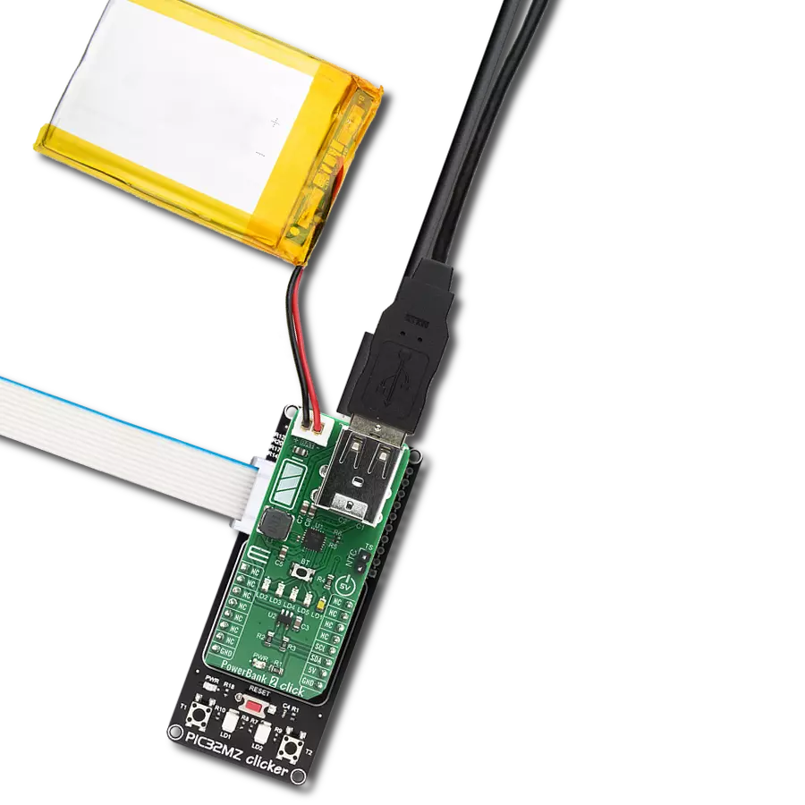
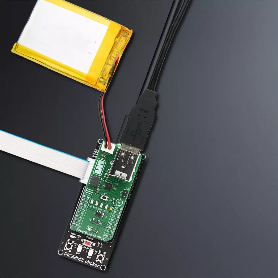
Project assembly

Start by selecting your development board and Click board™. Begin with the PIC32MZ clicker as your development board.


Software Support
Library Description
This library contains API for PowerBank 2 Click driver.
Key functions:
uint16_t powerbank2_read_data ( );- Function is used to read raw data from MCP3221.uint16_t powerbank2_read_voltage ( uint16_t v_ref );- Function is used to calculate voltage of the connected battery.
Open Source
Code example
The complete application code and a ready-to-use project are available through the NECTO Studio Package Manager for direct installation in the NECTO Studio. The application code can also be found on the MIKROE GitHub account.
/*!
 * \file
 * \brief Powerbank2 Click example
 *
 * # Description
 * This single chip includes a linear charger, a synchronous Boost with dual output load
 * management and a torch function support.
 *
 * The demo application is composed of two sections :
 *
 * ## Application Init
 * Initalizes I2C driver and makes an initial log.
 *
 * ## Application Task
 * This example shows the capabilities of the Power Bank 2 Click
 * by measuring voltage of the connected battery. In order to get correct calculations
 * the user should change "v_ref" value to his own power supply voltage.
 *
 * \author MikroE Team
 *
 */
// ------------------------------------------------------------------- INCLUDES

#include "board.h"
#include "log.h"
#include "powerbank2.h"

// ------------------------------------------------------------------ VARIABLES

static powerbank2_t powerbank2;
static log_t logger;

static uint16_t voltage;
static uint16_t v_ref = 5000; // milivolts

// ------------------------------------------------------ APPLICATION FUNCTIONS

void application_init ( void )
{
    log_cfg_t log_cfg;
    powerbank2_cfg_t cfg;

    /**
     * Logger initialization.
     * Default baud rate: 115200
     * Default log level: LOG_LEVEL_DEBUG
     * @note If USB_UART_RX and USB_UART_TX
     * are defined as HAL_PIN_NC, you will
     * need to define them manually for log to work.
     * See @b LOG_MAP_USB_UART macro definition for detailed explanation.
     */
    LOG_MAP_USB_UART( log_cfg );
    log_init( &logger, &log_cfg );
    log_info( &logger, "---- Application Init ----" );

    //  Click initialization.

    powerbank2_cfg_setup( &cfg );
    POWERBANK2_MAP_MIKROBUS( cfg, MIKROBUS_1 );
    powerbank2_init( &powerbank2, &cfg );
}

void application_task ( void )
{
    voltage = powerbank2_read_voltage( &powerbank2, v_ref );

    log_printf( &logger, "Battery voltage: %u mV\r\n", voltage );

    Delay_ms ( 1000 );
    Delay_ms ( 1000 );
}

int main ( void )
{
    /* Do not remove this line or clock might not be set correctly. */
    #ifdef PREINIT_SUPPORTED
    preinit();
    #endif

    application_init( );

    for ( ; ; )
    {
        application_task( );
    }

    return 0;
}

// ------------------------------------------------------------------------ END
Additional Support
Resources
Category:Battery charger


