Boost security and operational efficiency with our multifunctional switch keylock combined with MK64FN1M0VDC12
A key to versatility: The three-position lock that adapts to your needs

Published Oct 17, 2023
Click board™
Keylock 2 Click
Dev. board
Clicker 2 for Kinetis
Compiler
NECTO Studio
MCU
MK64FN1M0VDC12
Delve into the cutting-edge technology of a switch keylock that offers three distinct output states and its implications for various applications
A
A
Hardware Overview
How does it work?
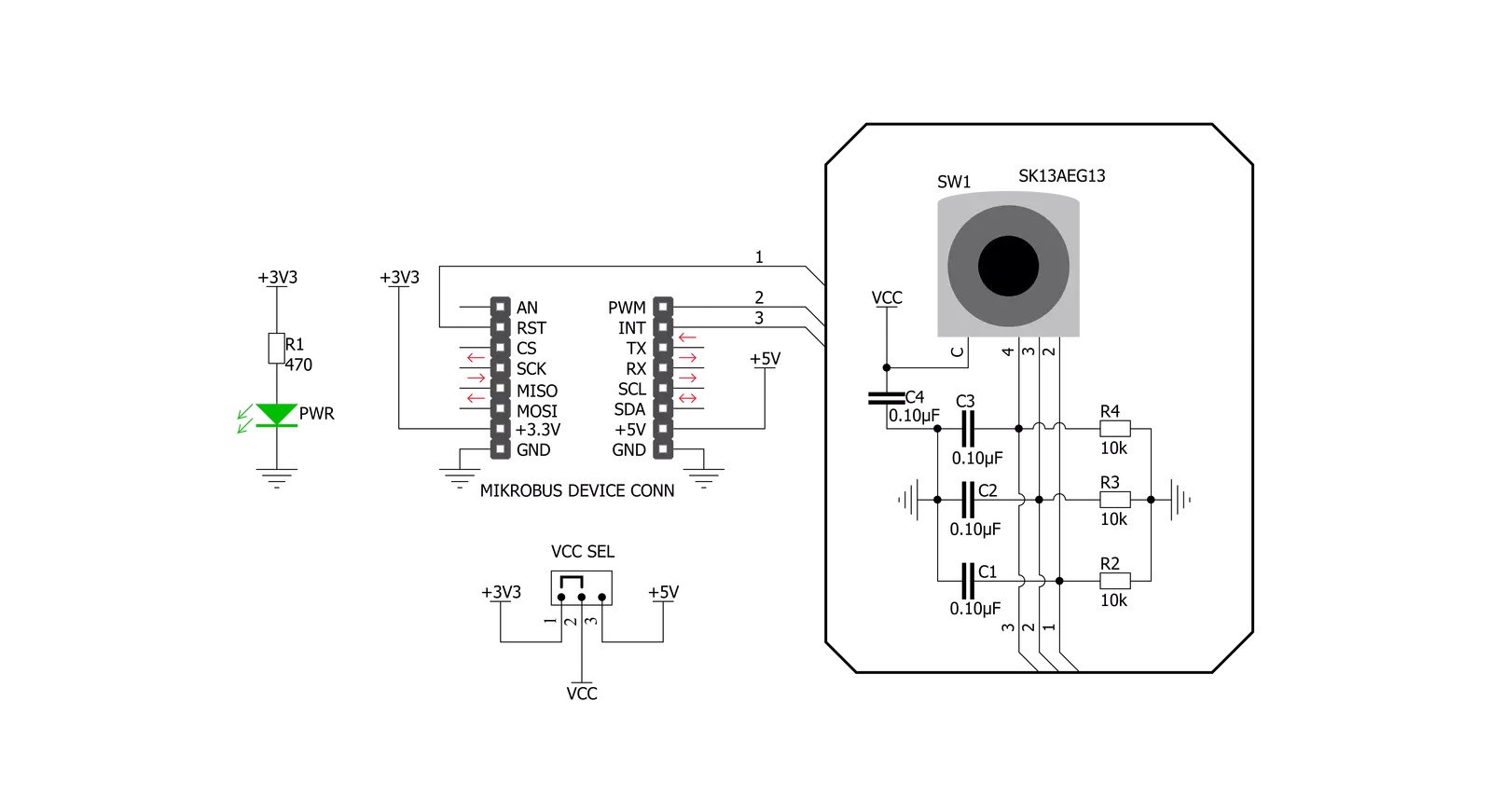
Keylock 2 Click is based on the SK13AEG13, a switch keylock from NKK Switches, with three position output states. The key can be removed from the lock in any of the three positions. The Click board package contains two keys and one protective cap. The SK13AEG13 key has hosing and brushing of high insulating material which withstands over 15 kilovolts of electrostatic discharge, thus providing antistatic protect for the main circuitry. This mechanism has mechanical life of 30,0000
cycles and electrical 20,0000 cycles with moving angle of 45° from position one to three there are no neutral positions. For switching task is in charge detent mechanism with its spring-operated steel ball, that gives district feel and crisp actuation for accurate switch setting as well as determining the exact position. This is very nice mechanical feedback that gives you more control during every switching movement. The SK13AEG13 casing is small and compact occupying very little
space on the PCB. Mouthing position of this mechanism in vertical (relative to PCB) with 9mm diameter smooth bushing on the top for elegant implementation. For interaction with the system this boards have three GPIO outputs connected to the mikroBUS™ pins for each position state keylock mechanism has. Logic level on the output pins can be selected with the VCC SEL jumper on the board (JP1) for the desired host board from 3.3V to 5V.


Features overview
Development board
Clicker 2 for Kinetis is a compact starter development board that brings the flexibility of add-on Click boards™ to your favorite microcontroller, making it a perfect starter kit for implementing your ideas. It comes with an onboard 32-bit ARM Cortex-M4F microcontroller, the MK64FN1M0VDC12 from NXP Semiconductors, two mikroBUS™ sockets for Click board™ connectivity, a USB connector, LED indicators, buttons, a JTAG programmer connector, and two 26-pin headers for interfacing with external electronics. Its compact design with clear and easily recognizable silkscreen markings allows you to build gadgets with unique functionalities and
features quickly. Each part of the Clicker 2 for Kinetis development kit contains the components necessary for the most efficient operation of the same board. In addition to the possibility of choosing the Clicker 2 for Kinetis programming method, using a USB HID mikroBootloader or an external mikroProg connector for Kinetis programmer, the Clicker 2 board also includes a clean and regulated power supply module for the development kit. It provides two ways of board-powering; through the USB Micro-B cable, where onboard voltage regulators provide the appropriate voltage levels to each component on the board, or
using a Li-Polymer battery via an onboard battery connector. All communication methods that mikroBUS™ itself supports are on this board, including the well-established mikroBUS™ socket, reset button, and several user-configurable buttons and LED indicators. Clicker 2 for Kinetis is an integral part of the Mikroe ecosystem, allowing you to create a new application in minutes. Natively supported by Mikroe software tools, it covers many aspects of prototyping thanks to a considerable number of different Click boards™ (over a thousand boards), the number of which is growing every day.

Microcontroller Overview
MCU Card / MCU

Architecture
ARM Cortex-M4
MCU Memory (KB)
1024
Silicon Vendor
NXP
Pin count
121
RAM (Bytes)
262144
Used MCU Pins
mikroBUS™ mapper
Take a closer look
Click board™ Schematic
Step by step
Project assembly

Start by selecting your development board and Click board™. Begin with the Clicker 2 for Kinetis as your development board.


Software Support
Library Description
This library contains API for Keylock 2 Click driver.
Key functions:
keylock2_get_pin_state- This function gets states of pins out1, out2 and out3 on Keylock 2 Click.keylock2_get_position- This function gets Position (First, Second, Third) of pins out1, out2 and out3 on Keylock 2 Click.
Open Source
Code example
The complete application code and a ready-to-use project are available through the NECTO Studio Package Manager for direct installation in the NECTO Studio. The application code can also be found on the MIKROE GitHub account.
/*!
 * \file
 * \brief Key Lock 2 Click example
 *
 * # Description
 * Keylock 2 Click carries antistatic process sealed keylock mechanism that
 * has three positions.
 *
 * The demo application is composed of two sections :
 *
 * ## Application Init
 * Initialization driver init.
 *
 * ## Application Task
 * Checks the current key position and logs the current position on the USB UART.
 *
 * \author MikroE Team
 *
 */
// ------------------------------------------------------------------- INCLUDES

#include "board.h"
#include "log.h"
#include "keylock2.h"

// ------------------------------------------------------------------ VARIABLES

static keylock2_t keylock2;
static log_t logger;

uint8_t old_position = 1;
uint8_t key_position;

// ------------------------------------------------------ APPLICATION FUNCTIONS

void application_init ( void )
{
    log_cfg_t log_cfg;
    keylock2_cfg_t cfg;

    /**
     * Logger initialization.
     * Default baud rate: 115200
     * Default log level: LOG_LEVEL_DEBUG
     * @note If USB_UART_RX and USB_UART_TX
     * are defined as HAL_PIN_NC, you will
     * need to define them manually for log to work.
     * See @b LOG_MAP_USB_UART macro definition for detailed explanation.
     */
    LOG_MAP_USB_UART( log_cfg );
    log_init( &logger, &log_cfg );
    log_info( &logger, "---- Application Init ----" );

    //  Click initialization.

    keylock2_cfg_setup( &cfg );
    KEYLOCK2_MAP_MIKROBUS( cfg, MIKROBUS_1 );
    keylock2_init( &keylock2, &cfg );
}

void application_task ( void )
{

    key_position = keylock2_get_position( &keylock2 );

    if ( old_position != key_position )
    {
        if ( key_position == KEYLOCK2_POSITION_1 )
        {
            log_printf( &logger, " -- FIRST position -- \r\n " );
        }
        else if ( key_position == KEYLOCK2_POSITION_2 )
        {
            log_printf( &logger, " -- SECOND position -- \r\n " );
        }
        else
        {
            log_printf( &logger, " -- THIRD position -- \r\n " );
        }
        old_position = key_position;
    }

    Delay_ms ( 500 );
}

int main ( void )
{
    /* Do not remove this line or clock might not be set correctly. */
    #ifdef PREINIT_SUPPORTED
    preinit();
    #endif

    application_init( );

    for ( ; ; )
    {
        application_task( );
    }

    return 0;
}


// ------------------------------------------------------------------------ END
Additional Support
Resources
Category:Pushbutton/Switches


