Convert the electrical power to a form that other devices can use with TPS62363 and PIC32MZ2048EFH100
Smart, compact, and efficient power management

Published Dec 10, 2023
Click board™
Smart Buck 2 Click
Dev. board
Clicker 2 for PIC32MZ
Compiler
NECTO Studio
MCU
PIC32MZ2048EFH100
Make your gadgets work efficiently by managing their power needs in a smart and compact way
A
A
Hardware Overview
How does it work?
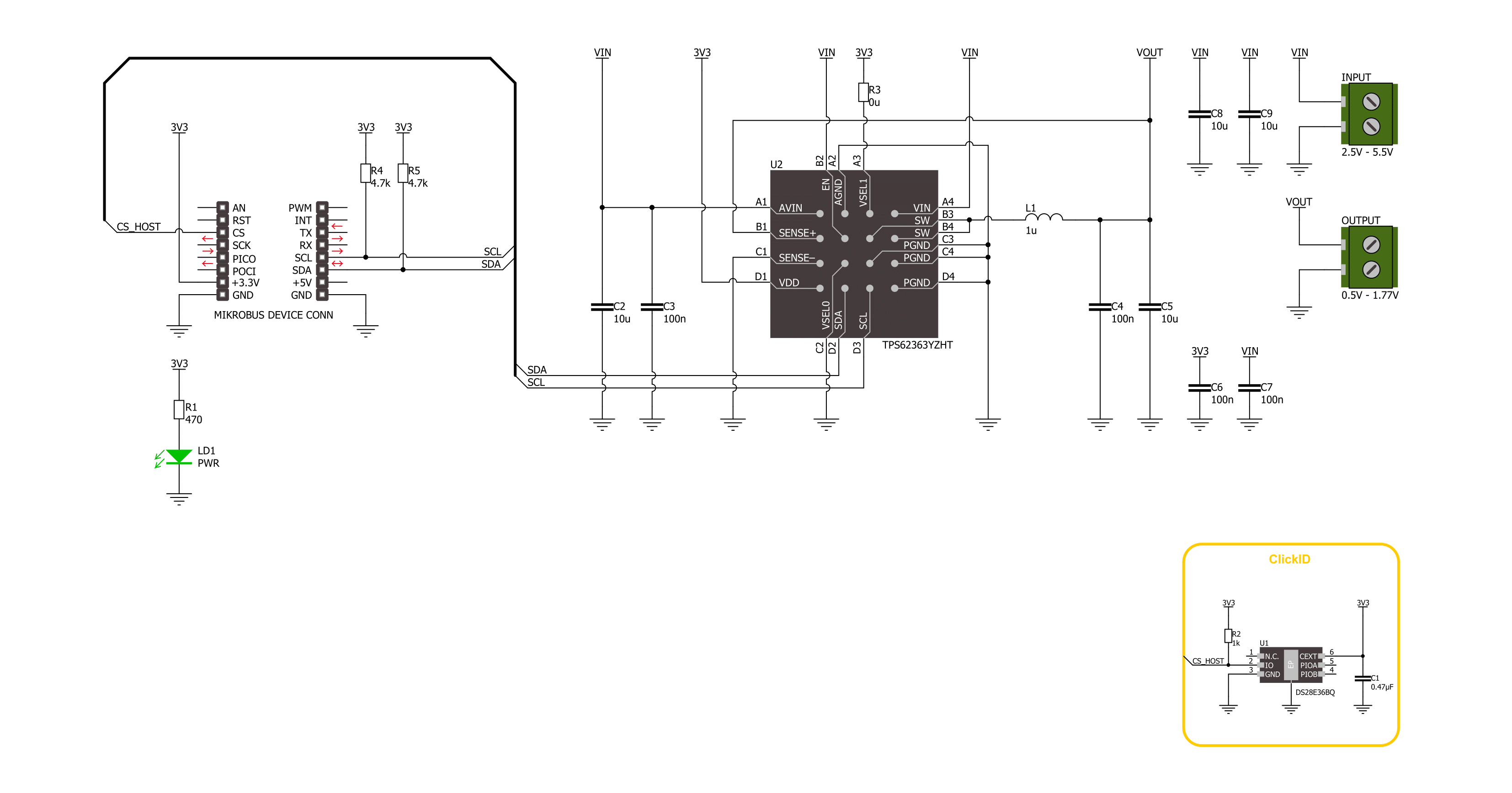
Smart Buck 2 Click is based on the TPS62363, a 3A processor supply with remote sense from Texas Instruments. The converter has a programable output voltage for digital voltage scaling in a range of 0.5V up to 1.77V in 10mV steps. It is focused on high-output voltage accuracy and features soft start, programmable slew rate at voltage transition, overtemperature protection, input undervoltage detection and lockout, differential load sensing, DCS-Control™ architecture for fast and precise transient regulation, and more. Also, it offers a high-efficiency step-down conversion, where the area of
highest efficiency is towards low currents while the processor is operating in retention mode, as well as towards the highest output currents, increasing the battery ON time. The TPS62363 converter features a power save mode to gain efficiency at light output current conditions. The device automatically transitions in both directions between pulse width modulation (PWM) operation at high load and pulse frequency modulation (PFM) operation at light load current. This maintains high efficiency at both light and heavy load currents. In PFM Mode, the device generates single switching pulses when require
to maintain the programmed output voltage. Smart Buck 2 Click uses a standard 2-wire I2C interface to communicate with the host MCU. The TPS62363 supports Standard, Fast, and High-Speed modes with a clock frequency of up to 3.4MHz. This Click board™ can be operated only with a 3.3V logic voltage level. The board must perform appropriate logic voltage level conversion before using MCUs with different logic levels. Also, this Click board™ comes equipped with a library containing easy-to-use functions and an example code that can be used for further development.

Features overview
Development board
Clicker 2 for PIC32MZ is a compact starter development board that brings the flexibility of add-on Click boards™ to your favorite microcontroller, making it a perfect starter kit for implementing your ideas. It comes with an onboard 32-bit PIC32MZ microcontroller from Microchip, two mikroBUS™ sockets for Click board™ connectivity, a USB connector, LED indicators, buttons, a mikroProg programmer connector, and two 26-pin headers for interfacing with external electronics. Its compact design with clear and easily recognizable silkscreen markings allows you to build gadgets with unique functionalities and features quickly.
Each part of the Clicker 2 for PIC32MZ development kit contains the components necessary for the most efficient operation of the same board. In addition to the possibility of choosing the Clicker 2 for PIC32MZ programming method, using a USB HID mikroBootloader or an external mikroProg connector for PIC, dsPIC, PIC32, the Clicker 2 board also includes a clean and regulated power supply module for the development kit. It provides two ways of board-powering; through the USB Micro-B cable, where onboard voltage regulators provide the appropriate voltage levels to each component on the board,
or using a Li-Polymer battery via an onboard battery connector. All communication methods that mikroBUS™ itself supports are on this board, including the well-established mikroBUS™ socket, reset button, and several user-configurable buttons and LED indicators. Clicker 2 for PIC32MZ is an integral part of the Mikroe ecosystem, allowing you to create a new application in minutes. Natively supported by Mikroe software tools, it covers many aspects of prototyping thanks to a considerable number of different Click boards™ (over a thousand boards), the number of which is growing every day.

Microcontroller Overview
MCU Card / MCU

Architecture
PIC32
MCU Memory (KB)
2048
Silicon Vendor
Microchip
Pin count
100
RAM (Bytes)
524288
Used MCU Pins
mikroBUS™ mapper
Take a closer look
Click board™ Schematic
Step by step
Project assembly

Start by selecting your development board and Click board™. Begin with the Clicker 2 for PIC32MZ as your development board.


Software Support
Library Description
This library contains API for Smart Buck 2 Click driver.
Key functions:
smartbuck2_set_voltage- Smart Buck 2 set voltage function.smartbuck2_get_voltage- Smart Buck 2 get voltage function.
Open Source
Code example
The complete application code and a ready-to-use project are available through the NECTO Studio Package Manager for direct installation in the NECTO Studio. The application code can also be found on the MIKROE GitHub account.
/*!
 * @file main.c
 * @brief Smart Buck 2 Click example
 *
 * # Description
 * This library contains API for the Smart Buck 2 Click board™.
 * This driver provides functions for device configurations
 * and for the sets and reads the output voltage.
 *
 * The demo application is composed of two sections :
 *
 * ## Application Init
 * Initialization of I2C module and log UART.
 * After driver initialization, the app executes a default configuration.
 *
 * ## Application Task
 * This example demonstrates the use of the Smart Buck 2 Click board™.
 * The demo application changes the output voltage in steps of 100mv every 3 seconds
 * and displays the output voltage value.
 * Results are sent to the UART Terminal, where you can track their changes.
 *
 * @author Nenad Filipovic
 *
 */

#include "board.h"
#include "log.h"
#include "smartbuck2.h"

#define DEMO_VOUT_STEP_100MV    100

static smartbuck2_t smartbuck2;
static log_t logger;
static uint16_t vout_mv = SMARTBUCK2_VOUT_MIN;

void application_init ( void )
{
    log_cfg_t log_cfg;  /**< Logger config object. */
    smartbuck2_cfg_t smartbuck2_cfg;  /**< Click config object. */

    /**
     * Logger initialization.
     * Default baud rate: 115200
     * Default log level: LOG_LEVEL_DEBUG
     * @note If USB_UART_RX and USB_UART_TX
     * are defined as HAL_PIN_NC, you will
     * need to define them manually for log to work.
     * See @b LOG_MAP_USB_UART macro definition for detailed explanation.
     */
    LOG_MAP_USB_UART( log_cfg );
    log_init( &logger, &log_cfg );
    log_info( &logger, " Application Init " );

    // Click initialization.
    smartbuck2_cfg_setup( &smartbuck2_cfg );
    SMARTBUCK2_MAP_MIKROBUS( smartbuck2_cfg, MIKROBUS_1 );
    if ( I2C_MASTER_ERROR == smartbuck2_init( &smartbuck2, &smartbuck2_cfg ) )
    {
        log_error( &logger, " Communication init." );
        for ( ; ; );
    }

    if ( SMARTBUCK2_ERROR == smartbuck2_default_cfg ( &smartbuck2 ) )
    {
        log_error( &logger, " Default configuration." );
        for ( ; ; );
    }

    log_info( &logger, " Application Task " );
    Delay_ms ( 100 );
}

void application_task ( void )
{
    if ( SMARTBUCK2_OK == smartbuck2_set_voltage( &smartbuck2, vout_mv ) )
    {
        Delay_ms ( 100 );
        if ( SMARTBUCK2_OK == smartbuck2_get_voltage( &smartbuck2, &vout_mv ) )
        {
            log_printf( &logger, " Output voltage: %u [mV]\r\n", vout_mv );
        }
    }
    vout_mv += DEMO_VOUT_STEP_100MV;
    if ( vout_mv > SMARTBUCK2_VOUT_MAX )
    {
        vout_mv = SMARTBUCK2_VOUT_MIN;
    }
    Delay_ms ( 1000 );
    Delay_ms ( 1000 );
    Delay_ms ( 1000 );
}

int main ( void )
{
    /* Do not remove this line or clock might not be set correctly. */
    #ifdef PREINIT_SUPPORTED
    preinit();
    #endif

    application_init( );

    for ( ; ; )
    {
        application_task( );
    }

    return 0;
}

// ------------------------------------------------------------------------ END


