Achieve the most reliable magnet angle measurements with AEAT-8800-Q24 and STM32F373VC
Detecting magnet rotation with ease

Published Sep 15, 2023
Click board™
Angle 4 Click
Dev. board
UNI Clicker
Compiler
NECTO Studio
MCU
STM32F373VC
Dive into the limitless possibilities unlocked by our magnet rotation sensing solution, empowering engineers and innovators to create smarter, more responsive systems
A
A
Hardware Overview
How does it work?
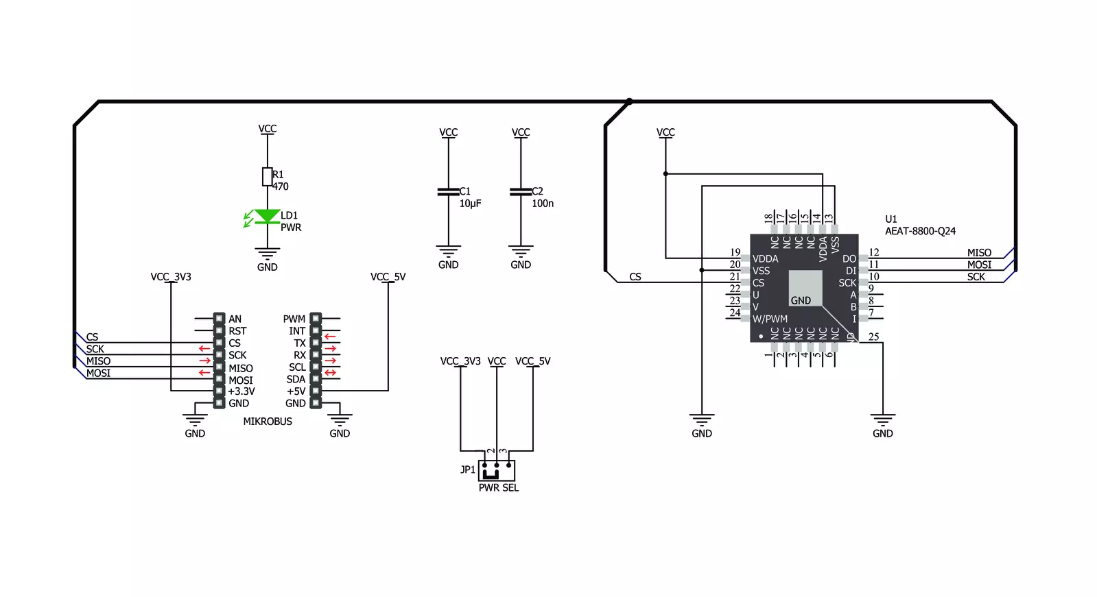
Angle 4 Click is based on the AEAT-8800-Q24, an integrated 10 to 16-bit programmable angular magnetic encoder from Broadcom. This sensor relies on integrated Hall elements and complex analog front end and digital signal processing, in order to provide absolute angular position over the industry standard SPI interface. The user has the ability to programmatically set the zero position, direction, hysteresis, and the resolution. This allows the Click board™ to be tailored according to needs for a range of different applications. The possibility to sense the rotational angle of a diametrically magnetized object parallel with the Click board™ surface, gives an opportunity to develop both contactless rotational and positional measurement applications, as well as the human-machine interfaces (HMI), such as the rotary encoders, digital potentiometers, and similar. The calibration is simple, and the AEAT-8800-Q24 datasheet provides a detailed explanation
how to calibrate the device by using a diametrically magnetized object (i.e. a magnetic disc), with its axis aligned to the center of the sensor. For the best results, the magnet properties should be according to specifications in the datasheet. Once calibrated, it can be permanently used, with no additional recalibrations. The AEAT-8800-Q24 uses the non-volatile one-time programming memory during the operation. It contains registers with the calibration values, zero offsets, resolution and so on. All the OTP locations have their shadow locations, which allow writing, but only when the unlock command is issued (writing 0xAB to the location 0x10). However, the values will be lost after the power cycle and will be rewritten with the values contained in the OTP memory. The library provided with Angle 4 click offers several simple and useful functions, among which is the angle4_calibration function, which will automatically program the direction and the
resolution parameters to the OTP memory, passed as argumetns to this function. However, the OTP memory will not be permanently written, unless appropriate programming voltage is applied to the VDDP pin. Since the OTP memory can be programmed only once, a thorough understanding of the OTP programming process is required. More information about the OTP programming process can be found in the AEAT-8800-Q24 datasheet. This Click board™ can operate with either 3.3V or 5V logic voltage levels selected via the PWR SEL jumper. This way, both 3.3V and 5V capable MCUs can use the communication lines properly. Also, this Click board™ comes equipped with a library containing easy-to-use functions and an example code that can be used as a reference for further development.


Features overview
Development board
UNI Clicker is a compact development board designed as a complete solution that brings the flexibility of add-on Click boards™ to your favorite microcontroller, making it a perfect starter kit for implementing your ideas. It supports a wide range of microcontrollers, such as different ARM, PIC32, dsPIC, PIC, and AVR from various vendors like Microchip, ST, NXP, and TI (regardless of their number of pins), four mikroBUS™ sockets for Click board™ connectivity, a USB connector, LED indicators, buttons, a debugger/programmer connector, and two 26-pin headers for interfacing with external electronics. Thanks to innovative manufacturing technology, it allows you to build
gadgets with unique functionalities and features quickly. Each part of the UNI Clicker development kit contains the components necessary for the most efficient operation of the same board. In addition to the possibility of choosing the UNI Clicker programming method, using a third-party programmer or CODEGRIP/mikroProg connected to onboard JTAG/SWD header, the UNI Clicker board also includes a clean and regulated power supply module for the development kit. It provides two ways of board-powering; through the USB Type-C (USB-C) connector, where onboard voltage regulators provide the appropriate voltage levels to each component on the board, or using a Li-Po/Li
Ion battery via an onboard battery connector. All communication methods that mikroBUS™ itself supports are on this board (plus USB HOST/DEVICE), including the well-established mikroBUS™ socket, a standardized socket for the MCU card (SiBRAIN standard), and several user-configurable buttons and LED indicators. UNI Clicker is an integral part of the Mikroe ecosystem, allowing you to create a new application in minutes. Natively supported by Mikroe software tools, it covers many aspects of prototyping thanks to a considerable number of different Click boards™ (over a thousand boards), the number of which is growing every day.

Microcontroller Overview
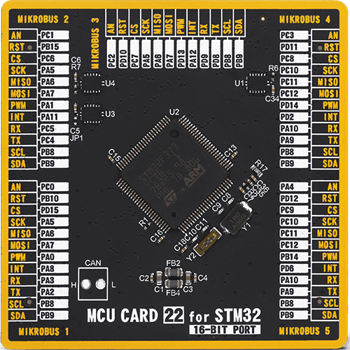
MCU Card / MCU
Type
8th Generation
Architecture
ARM Cortex-M4
MCU Memory (KB)
256
Silicon Vendor
STMicroelectronics
Pin count
100
RAM (Bytes)
49152
Used MCU Pins
mikroBUS™ mapper
Take a closer look
Click board™ Schematic
Step by step
Project assembly

Start by selecting your development board and Click board™. Begin with the UNI Clicker as your development board.


Track your results in real time
Application Output
1. Application Output - In Debug mode, the 'Application Output' window enables real-time data monitoring, offering direct insight into execution results. Ensure proper data display by configuring the environment correctly using the provided tutorial.

2. UART Terminal - Use the UART Terminal to monitor data transmission via a USB to UART converter, allowing direct communication between the Click board™ and your development system. Configure the baud rate and other serial settings according to your project's requirements to ensure proper functionality. For step-by-step setup instructions, refer to the provided tutorial.

3. Plot Output - The Plot feature offers a powerful way to visualize real-time sensor data, enabling trend analysis, debugging, and comparison of multiple data points. To set it up correctly, follow the provided tutorial, which includes a step-by-step example of using the Plot feature to display Click board™ readings. To use the Plot feature in your code, use the function: plot(*insert_graph_name*, variable_name);. This is a general format, and it is up to the user to replace 'insert_graph_name' with the actual graph name and 'variable_name' with the parameter to be displayed.

Software Support
Library Description
This library contains API for Angle 4 Click driver.
Key functions:
angle4_start_mesuremenet- This function is used to start measurement modeangle4_get_new_angle- This function is used to retrieve Angle value depending on the given resolutionangle4_read_byte- This function is used to read single byte of Data on the desired address.
Open Source
Code example
The complete application code and a ready-to-use project are available through the NECTO Studio Package Manager for direct installation in the NECTO Studio. The application code can also be found on the MIKROE GitHub account.
/*!
 * \file
 * \brief Angle4 Click example
 *
 * # Description
 * This application enables use of angular magnetic rotary sensor, which can be used as a rotary encoder.
 *
 * The demo application is composed of two sections :
 *
 * ## Application Init
 * Driver intialization, standard configurations and start measurement
 *
 * ## Application Task
 * Reads Angle in degreeses and logs data to USBUART every 200 ms.
 *
 * \author MikroE Team
 *
 */
// ------------------------------------------------------------------- INCLUDES

#include "board.h"
#include "log.h"
#include "angle4.h"

// ------------------------------------------------------------------ VARIABLES

static angle4_t angle4;
static log_t logger;

// ------------------------------------------------------ APPLICATION FUNCTIONS

void application_init ( void )
{
    log_cfg_t log_cfg;
    angle4_cfg_t cfg;

    /**
     * Logger initialization.
     * Default baud rate: 115200
     * Default log level: LOG_LEVEL_DEBUG
     * @note If USB_UART_RX and USB_UART_TX
     * are defined as HAL_PIN_NC, you will
     * need to define them manually for log to work.
     * See @b LOG_MAP_USB_UART macro definition for detailed explanation.
     */
    LOG_MAP_USB_UART( log_cfg );
    log_init( &logger, &log_cfg );
    log_info( &logger, "---- Application Init ----" );

    //  Click initialization.

    angle4_cfg_setup( &cfg );
    ANGLE4_MAP_MIKROBUS( cfg, MIKROBUS_1 );
    angle4_init( &angle4, &cfg );

    angle4_default_cfg( &angle4, ANGLE4_CCFG2_DIR_COUNTER_CLOCKWISE_ROTATION,\
                                 ANGLE4_CCFG2_ABS_RESOLUTION_14bit );
    log_printf( &logger, " --- Start measurement \r\n");

    angle4_start_mesuremenet( &angle4 );
}

void application_task ( void )
{
    //  Task implementation.

    uint16_t angle_value;

    angle4_get_new_angle( &angle4, &angle_value );
    log_printf( &logger, " Angle : %d deg\r\n", angle_value );
    Delay_ms ( 200 );
}

int main ( void )
{
    /* Do not remove this line or clock might not be set correctly. */
    #ifdef PREINIT_SUPPORTED
    preinit();
    #endif

    application_init( );

    for ( ; ; )
    {
        application_task( );
    }

    return 0;
}


// ------------------------------------------------------------------------ END


