Create smart and responsive environments with TSL2591 and STM32F756ZG that adapt to changing ambient conditions
The light whisperer: Crafting perfect ambiance with ease!

Published Sep 19, 2023
Click board™
Ambient 21 Click
Dev. board
UNI Clicker
Compiler
NECTO Studio
MCU
STM32F756ZG
Integrate ambient light sensing into home automation systems for enhanced security by adjusting outdoor lighting based on environmental conditions
A
A
Hardware Overview
How does it work?
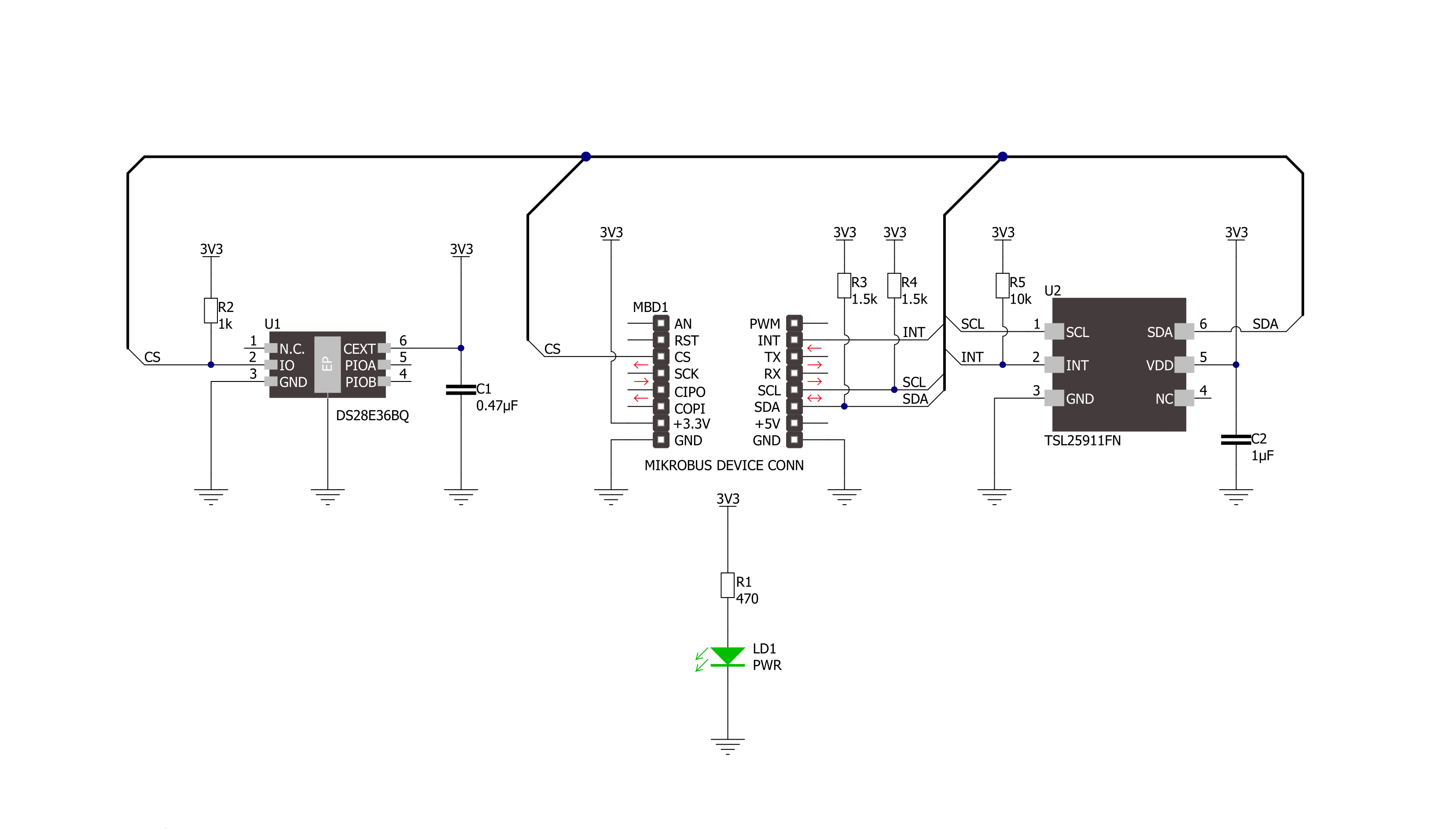
Ambient 21 Click is based on the TSL2591, a high-sensitivity light-to-digital converter from ams AG. The TSL2591 provides ambient light sensing (ALS) that approximates the human eye response to light intensity under various lighting conditions and through different attenuation materials. It has a flexible and wide operating range of up to 88klx with the highest sensitivity of 188μlx, even when mounted behind dark glass. This sensor comes in a UV-rejection package, enabling its operation in IR light environments, making this board most suitable for various brightness control functions, helping to reduce power consumption. The TSL2591 contains two integrating analog-to-digital converters (ADC) that integrate currents from two photodiodes: one broadband photodiode (visible plus infrared) and one infrared-response
photodiode. These ADCs convert the photodiode currents into a digital output representing the irradiance measured on each channel. Ambient 21 Click communicates with an MCU using the standard I2C 2-Wire interface to read data and configure settings, supporting Standard Mode operation with a clock frequency of 100kHz and Fast Mode up to 400kHz. Integration of both channels co-occurs. The conversion result is transferred to the appropriate channel data registers upon completion of the conversion cycle. The transfers are double-buffered to ensure that the integrity of the data is maintained. After the transfer, the device automatically begins the next integration cycle. This sensor also supports an interrupt feature, routed to the INT pin on the mikroBUS™ socket, that simplifies and improves
system efficiency by eliminating the need to poll a sensor for a light intensity value. The purpose of the interrupt function is to detect a meaningful change in light intensity, where the user can define the concept of a significant change in light intensity and time or persistence. Users can define a threshold above and below the current light level, where an interrupt is generated when the conversion value exceeds either of these limits. This Click board™ can be operated only with a 3.3V logic voltage level. The board must perform appropriate logic voltage level conversion before using MCUs with different logic levels. Also, it comes equipped with a library containing functions and an example code that can be used as a reference for further development.


Features overview
Development board
UNI Clicker is a compact development board designed as a complete solution that brings the flexibility of add-on Click boards™ to your favorite microcontroller, making it a perfect starter kit for implementing your ideas. It supports a wide range of microcontrollers, such as different ARM, PIC32, dsPIC, PIC, and AVR from various vendors like Microchip, ST, NXP, and TI (regardless of their number of pins), four mikroBUS™ sockets for Click board™ connectivity, a USB connector, LED indicators, buttons, a debugger/programmer connector, and two 26-pin headers for interfacing with external electronics. Thanks to innovative manufacturing technology, it allows you to build
gadgets with unique functionalities and features quickly. Each part of the UNI Clicker development kit contains the components necessary for the most efficient operation of the same board. In addition to the possibility of choosing the UNI Clicker programming method, using a third-party programmer or CODEGRIP/mikroProg connected to onboard JTAG/SWD header, the UNI Clicker board also includes a clean and regulated power supply module for the development kit. It provides two ways of board-powering; through the USB Type-C (USB-C) connector, where onboard voltage regulators provide the appropriate voltage levels to each component on the board, or using a Li-Po/Li
Ion battery via an onboard battery connector. All communication methods that mikroBUS™ itself supports are on this board (plus USB HOST/DEVICE), including the well-established mikroBUS™ socket, a standardized socket for the MCU card (SiBRAIN standard), and several user-configurable buttons and LED indicators. UNI Clicker is an integral part of the Mikroe ecosystem, allowing you to create a new application in minutes. Natively supported by Mikroe software tools, it covers many aspects of prototyping thanks to a considerable number of different Click boards™ (over a thousand boards), the number of which is growing every day.

Microcontroller Overview
MCU Card / MCU
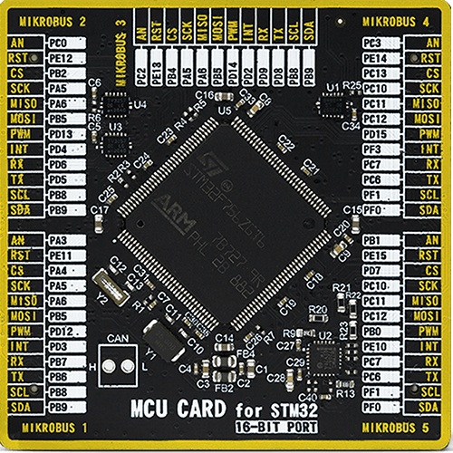
Type
8th Generation
Architecture
ARM Cortex-M7
MCU Memory (KB)
1024
Silicon Vendor
STMicroelectronics
Pin count
144
RAM (Bytes)
327680
Used MCU Pins
mikroBUS™ mapper
Take a closer look
Click board™ Schematic
Step by step
Project assembly

Start by selecting your development board and Click board™. Begin with the UNI Clicker as your development board.


Track your results in real time
Application Output
1. Application Output - In Debug mode, the 'Application Output' window enables real-time data monitoring, offering direct insight into execution results. Ensure proper data display by configuring the environment correctly using the provided tutorial.

2. UART Terminal - Use the UART Terminal to monitor data transmission via a USB to UART converter, allowing direct communication between the Click board™ and your development system. Configure the baud rate and other serial settings according to your project's requirements to ensure proper functionality. For step-by-step setup instructions, refer to the provided tutorial.

3. Plot Output - The Plot feature offers a powerful way to visualize real-time sensor data, enabling trend analysis, debugging, and comparison of multiple data points. To set it up correctly, follow the provided tutorial, which includes a step-by-step example of using the Plot feature to display Click board™ readings. To use the Plot feature in your code, use the function: plot(*insert_graph_name*, variable_name);. This is a general format, and it is up to the user to replace 'insert_graph_name' with the actual graph name and 'variable_name' with the parameter to be displayed.

Software Support
Library Description
This library contains API for Ambient 21 Click driver.
Key functions:
ambient21_get_int_pin- This function returns the INT pin logic stateambient21_read_raw_data- This function checks if the data is ready and then reads the raw ADC data from two channelsambient21_measure_light_level- This function reads the raw ADC data from two channels and then measures the light level in lux based on those readings.
Open Source
Code example
The complete application code and a ready-to-use project are available through the NECTO Studio Package Manager for direct installation in the NECTO Studio. The application code can also be found on the MIKROE GitHub account.
/*!
 * @file main.c
 * @brief Ambient 21 Click example
 *
 * # Description
 * This example demonstrates the use of Ambient 21 Click board by measuring
 * the ambient light level in Lux.
 *
 * The demo application is composed of two sections :
 *
 * ## Application Init
 * Initializes the driver and performs the Click default configuration.
 *
 * ## Application Task
 * Waits for the data ready interrupt, then reads the ambient light level in Lux
 * and displays the results on the USB UART. By default, the data ready interrupt triggers
 * upon every ADC cycle which occurs every 200ms.
 *
 * @author Stefan Filipovic
 *
 */

#include "board.h"
#include "log.h"
#include "ambient21.h"

static ambient21_t ambient21;
static log_t logger;

void application_init ( void )
{
    log_cfg_t log_cfg;  /**< Logger config object. */
    ambient21_cfg_t ambient21_cfg;  /**< Click config object. */

    /**
     * Logger initialization.
     * Default baud rate: 115200
     * Default log level: LOG_LEVEL_DEBUG
     * @note If USB_UART_RX and USB_UART_TX
     * are defined as HAL_PIN_NC, you will
     * need to define them manually for log to work.
     * See @b LOG_MAP_USB_UART macro definition for detailed explanation.
     */
    LOG_MAP_USB_UART( log_cfg );
    log_init( &logger, &log_cfg );
    log_info( &logger, " Application Init " );

    // Click initialization.
    ambient21_cfg_setup( &ambient21_cfg );
    AMBIENT21_MAP_MIKROBUS( ambient21_cfg, MIKROBUS_1 );
    if ( I2C_MASTER_ERROR == ambient21_init( &ambient21, &ambient21_cfg ) )
    {
        log_error( &logger, " Communication init." );
        for ( ; ; );
    }

    if ( AMBIENT21_ERROR == ambient21_default_cfg ( &ambient21 ) )
    {
        log_error( &logger, " Default configuration." );
        for ( ; ; );
    }

    log_info( &logger, " Application Task " );
}

void application_task ( void )
{
    uint16_t lux;
    if ( !ambient21_get_int_pin ( &ambient21 ) )
    {
        if ( AMBIENT21_OK == ambient21_measure_light_level ( &ambient21, &lux ) )
        {
            log_printf ( &logger, " Ambient light level [Lux]: %u\r\n\n", lux );
        }
    }
}

int main ( void )
{
    /* Do not remove this line or clock might not be set correctly. */
    #ifdef PREINIT_SUPPORTED
    preinit();
    #endif

    application_init( );

    for ( ; ; )
    {
        application_task( );
    }

    return 0;
}

// ------------------------------------------------------------------------ END


