Achieve reliable movement or rotation encoding with TCUT1600X01 and PIC18F47Q10
Decode moves with precision
Published Sep 21, 2023
Click board™
Opto encoder Click
Dev. board
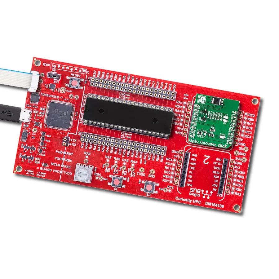
Curiosity HPC
Compiler
NECTO Studio
MCU
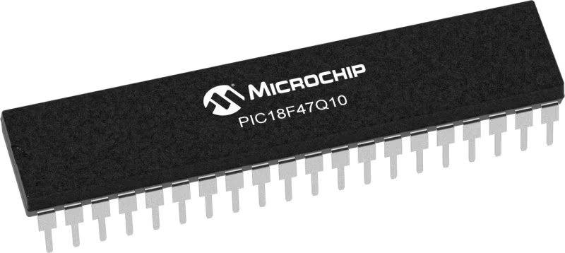
PIC18F47Q10
Achieve unparalleled levels of precision and accuracy in your motion tracking and control systems
A
A
Hardware Overview
How does it work?
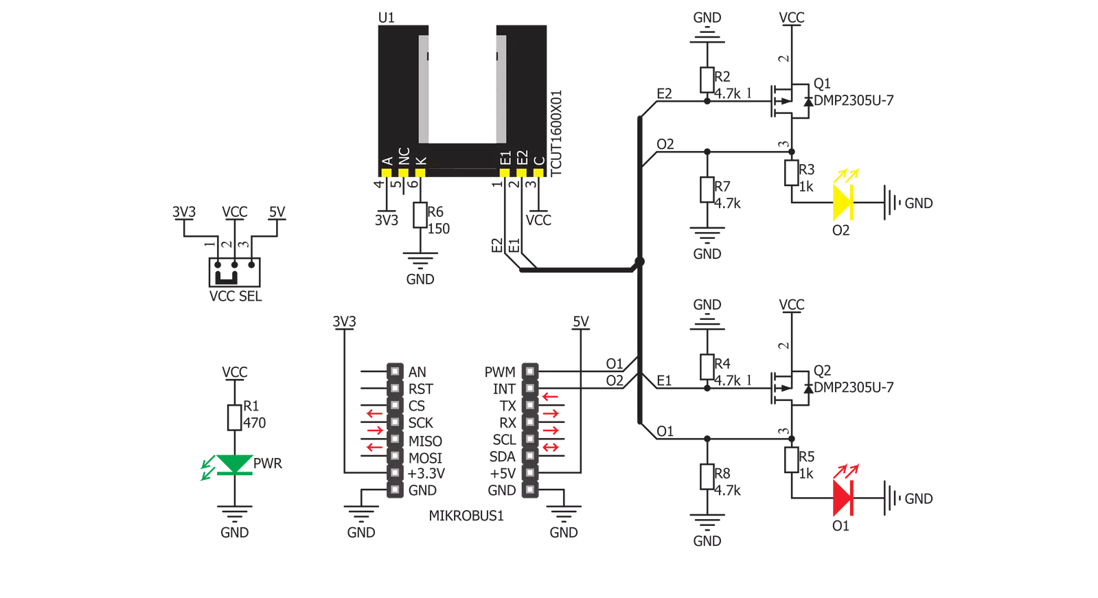
Opto encoder Click is based on the TCUT1600X01, a tall dome dual channel transmissive optical sensor with phototransistor outputs from Vishay. This sensor is equipped with one infrared LED with the wavelength of 950nm, and two phototransistors. These phototransistors are positioned behind two small slits on the sensor, on the opposite side of the LED. They form two separate channels. When the transistors get illuminated by the LED, they become conductive. The collectors of these transistors are connected to the same pin, while their emitters are routed to two separate output pins of the TCUT1600X01 - E1 and E2. This allows the activity on both channels to be detected by the host MCU. Since the signals of these two output channels are not enough to drive pins
on a host MCU, the Click board™ features two additional MOSFETs. These MOSFETs are also used to drive two additional LEDs, which indicate activity of each channel. E1 and E2 pins are routed to the MOSFET gate pins, while the MOSFET drains are routed to the mikroBUS™ PWM and INT pins. These pins are pulled to a LOW logic level by the pull-down resistors, to avoid floating. Signal encoding itself is done by the host MCU. Having two optical sensing channels, Opto Encoder click has the ability of both speed and direction encoding. The most common usage is encoding of the step motor position: a cylinder with slits is physically mounted above the sensor so that the LED can illuminate the phototransistors only through these slits. By rotating this cylinder,
the light beam will be blocked periodically. The single sensor output will be a pulse train, while the cylinder is rotating. Having two photo sensors physically distanced by a small amount, allows the pulse signal of the first sensor to be either delayed or expedited with respect to the pulse on the second sensor, depending on the rotational direction. This Click board™ can operate with either 3.3V or 5V logic voltage levels selected via the VCC SEL jumper. This way, both 3.3V and 5V capable MCUs can use the communication lines properly. Also, this Click board™ comes equipped with a library containing easy-to-use functions and an example code that can be used as a reference for further development.


Features overview
Development board
Curiosity HPC, standing for Curiosity High Pin Count (HPC) development board, supports 28- and 40-pin 8-bit PIC MCUs specially designed by Microchip for the needs of rapid development of embedded applications. This board has two unique PDIP sockets, surrounded by dual-row expansion headers, allowing connectivity to all pins on the populated PIC MCUs. It also contains a powerful onboard PICkit™ (PKOB), eliminating the need for an external programming/debugging tool, two mikroBUS™ sockets for Click board™ connectivity, a USB connector, a set of indicator LEDs, push button switches and a variable potentiometer. All
these features allow you to combine the strength of Microchip and Mikroe and create custom electronic solutions more efficiently than ever. Each part of the Curiosity HPC development board contains the components necessary for the most efficient operation of the same board. An integrated onboard PICkit™ (PKOB) allows low-voltage programming and in-circuit debugging for all supported devices. When used with the MPLAB® X Integrated Development Environment (IDE, version 3.0 or higher) or MPLAB® Xpress IDE, in-circuit debugging allows users to run, modify, and troubleshoot their custom software and hardware
quickly without the need for additional debugging tools. Besides, it includes a clean and regulated power supply block for the development board via the USB Micro-B connector, alongside all communication methods that mikroBUS™ itself supports. Curiosity HPC development board allows you to create a new application in just a few steps. Natively supported by Microchip software tools, it covers many aspects of prototyping thanks to many number of different Click boards™ (over a thousand boards), the number of which is growing daily.

Microcontroller Overview
MCU Card / MCU
Architecture
PIC
MCU Memory (KB)
128
Silicon Vendor
Microchip
Pin count
40
RAM (Bytes)
3615
Used MCU Pins
mikroBUS™ mapper
Take a closer look
Click board™ Schematic
Step by step
Project assembly

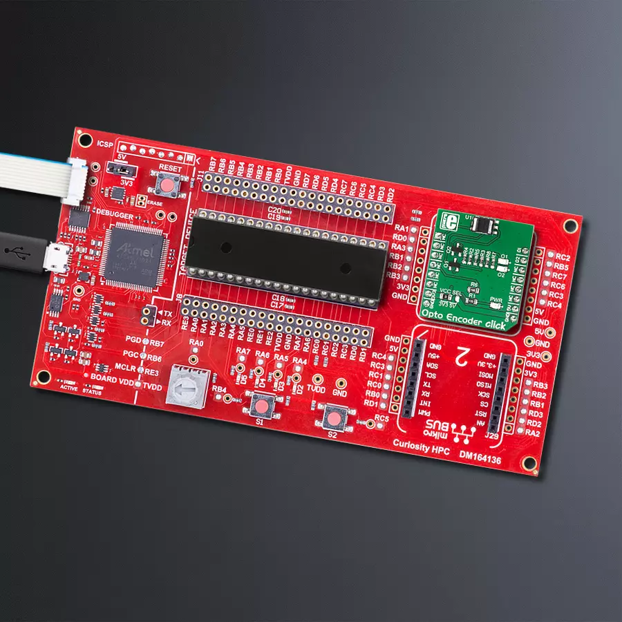
Start by selecting your development board and Click board™. Begin with the Curiosity HPC as your development board.


Track your results in real time
Application Output
1. Application Output - In Debug mode, the 'Application Output' window enables real-time data monitoring, offering direct insight into execution results. Ensure proper data display by configuring the environment correctly using the provided tutorial.

2. UART Terminal - Use the UART Terminal to monitor data transmission via a USB to UART converter, allowing direct communication between the Click board™ and your development system. Configure the baud rate and other serial settings according to your project's requirements to ensure proper functionality. For step-by-step setup instructions, refer to the provided tutorial.

3. Plot Output - The Plot feature offers a powerful way to visualize real-time sensor data, enabling trend analysis, debugging, and comparison of multiple data points. To set it up correctly, follow the provided tutorial, which includes a step-by-step example of using the Plot feature to display Click board™ readings. To use the Plot feature in your code, use the function: plot(*insert_graph_name*, variable_name);. This is a general format, and it is up to the user to replace 'insert_graph_name' with the actual graph name and 'variable_name' with the parameter to be displayed.

Software Support
Library Description
This library contains API for Opto encoder Click driver.
Key functions:
optoencoder_getO1- Function for reading O1 stateoptoencoder_init_dev- Initialization functionoptoencoder_get_position- Function for reading the position of the encoder
Open Source
Code example
The complete application code and a ready-to-use project are available through the NECTO Studio Package Manager for direct installation in the NECTO Studio. The application code can also be found on the MIKROE GitHub account.
/*!
 * \file
 * \brief Opto Encoder Click example
 *
 * # Description
 * This application is used to encode motion or rotation.
 *
 * The demo application is composed of two sections :
 *
 * ## Application Init
 * Initializes driver and opto encoder.
 *
 * ## Application Task
 * Depending on the direction of the movement it increments/decrements the step counter.
 *
 * \author MikroE Team
 *
 */
// ------------------------------------------------------------------- INCLUDES

#include "board.h"
#include "log.h"
#include "optoencoder.h"

// ------------------------------------------------------------------ VARIABLES

static optoencoder_t optoencoder;
static log_t logger;
static int16_t old_step = 0;

// ------------------------------------------------------ APPLICATION FUNCTIONS

void application_init ( void )
{
    log_cfg_t log_cfg;
    optoencoder_cfg_t cfg;

    /**
     * Logger initialization.
     * Default baud rate: 115200
     * Default log level: LOG_LEVEL_DEBUG
     * @note If USB_UART_RX and USB_UART_TX
     * are defined as HAL_PIN_NC, you will
     * need to define them manually for log to work.
     * See @b LOG_MAP_USB_UART macro definition for detailed explanation.
     */
    LOG_MAP_USB_UART( log_cfg );
    log_init( &logger, &log_cfg );
    log_info(&logger, "---- Application Init ----");

    //  Click initialization.

    optoencoder_cfg_setup( &cfg );
    OPTOENCODER_MAP_MIKROBUS( cfg, MIKROBUS_1 );
    optoencoder_init( &optoencoder, &cfg );

    optoencoder_init_dev( &optoencoder );
}

void application_task ( )
{
    int16_t new_step;
    new_step = optoencoder_get_position( &optoencoder );
    if ( old_step != new_step)
    {
        log_printf( &logger, "Step: %d \r\n", new_step );
        old_step = new_step;
    }
}

int main ( void )
{
    /* Do not remove this line or clock might not be set correctly. */
    #ifdef PREINIT_SUPPORTED
    preinit();
    #endif

    application_init( );

    for ( ; ; )
    {
        application_task( );
    }

    return 0;
}

// ------------------------------------------------------------------------ END
Additional Support
Resources
Category:Optical


