Gain a clear view of AC or DC current profiles using TMCS1108A2U and PIC18F46K40
Efficiency amplified through advanced current sensing
Published Nov 01, 2023
Click board™
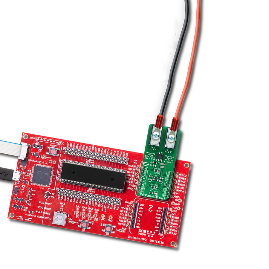
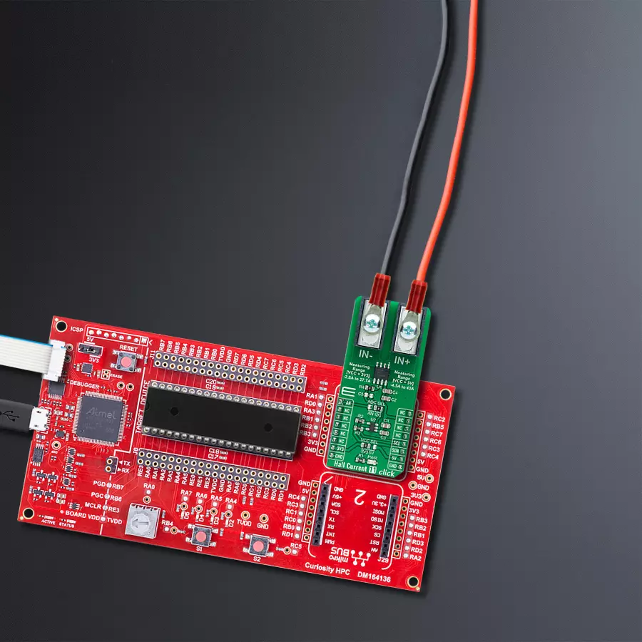
Hall Current 11 Click
Dev. board
Curiosity HPC
Compiler
NECTO Studio
MCU
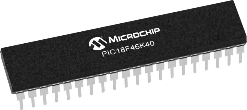
PIC18F46K40
Elevate your engineering projects with our Hall-effect current sensing solution, delivering accurate and actionable current data for effective system design, optimization, and maintenance
A
A
Hardware Overview
How does it work?
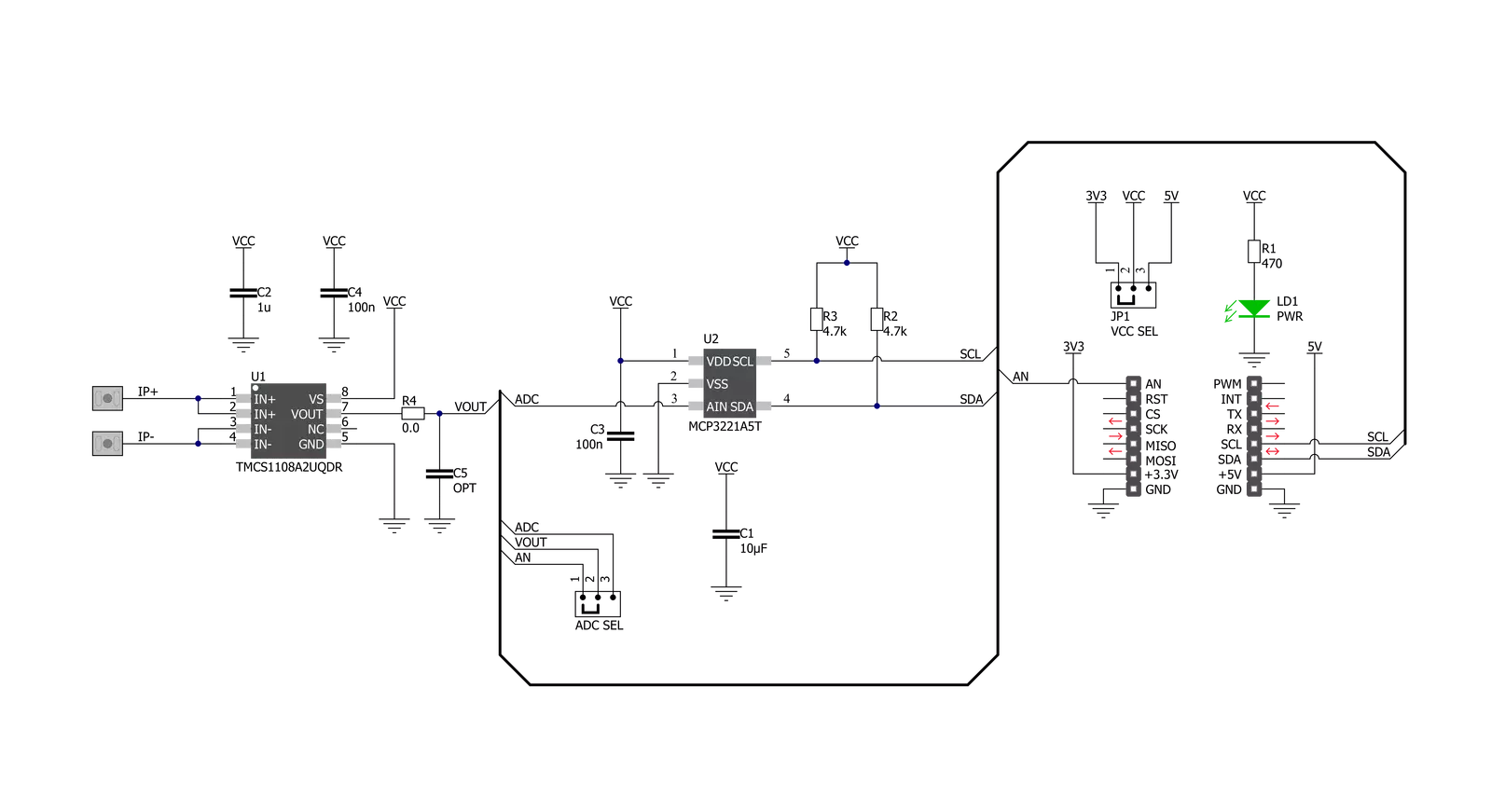
Hall Current 11 Click is based on the TMCS1108A2U, a precision Hall-effect current sensor featuring a 100V functional isolation working voltage, <3% full-scale error across temperature, and both unidirectional and bidirectional current sensing from Texas Instruments. The input current flows through a 1.8mΩ resistance conductor between the isolated input current pins, minimizing power loss and thermal dissipation. The magnetic field generated by the input current is sensed by a Hall sensor and amplified by a precision integrated signal chain. The TMCS1108A2U can be used for both AC and DC current measurements with a bandwidth of 80kHz. The TMCS1108A2U is optimized for high accuracy and temperature stability, with both offset and sensitivity compensated across the entire operating
temperature range. Based on the selected logic voltage VCC, the TMCS1108A2U allows the user to measure current in two appropriate ranges, where after that, can process the output signal in analog or digital form. With the selected logic voltage of 3.3V, it is possible to measure the current from -2.8A to 27.7A, while with the chosen 5V, it is possible to measure it in the range from -4.5A to 43A. The analog output signal of the TMCS1108A2U can be converted to a digital value using MCP3221, a successive approximation A/D converter with a 12-bit resolution from Microchip using a 2-wire I2C compatible interface, or can be sent directly to an analog pin of the mikroBUS™ socket labeled as AN. Selection can be performed by onboard SMD jumper labeled ADC SEL to an appropriate position marked as AN and I2C.
The MCP3221 provides one single-ended input with low power consumption, a low maximum conversion current, and a Standby current of 250μA and 1μA, respectively. Data can be transferred at up to 100kbit/s in the Standard and 400kbit/s in the Fast Mode. Also, maximum sample rates of 22.3kSPS with the MCP3221 are possible in a Continuous-Conversion Mode with a clock rate of 400kHz. This Click board™ can operate with either 3.3V or 5V logic voltage levels selected via the VCC SEL jumper. This way, both 3.3V and 5V capable MCUs can use the communication lines properly. Also, this Click board™ comes equipped with a library containing easy-to-use functions and an example code that can be used, as a reference, for further development.


Features overview
Development board
Curiosity HPC, standing for Curiosity High Pin Count (HPC) development board, supports 28- and 40-pin 8-bit PIC MCUs specially designed by Microchip for the needs of rapid development of embedded applications. This board has two unique PDIP sockets, surrounded by dual-row expansion headers, allowing connectivity to all pins on the populated PIC MCUs. It also contains a powerful onboard PICkit™ (PKOB), eliminating the need for an external programming/debugging tool, two mikroBUS™ sockets for Click board™ connectivity, a USB connector, a set of indicator LEDs, push button switches and a variable potentiometer. All
these features allow you to combine the strength of Microchip and Mikroe and create custom electronic solutions more efficiently than ever. Each part of the Curiosity HPC development board contains the components necessary for the most efficient operation of the same board. An integrated onboard PICkit™ (PKOB) allows low-voltage programming and in-circuit debugging for all supported devices. When used with the MPLAB® X Integrated Development Environment (IDE, version 3.0 or higher) or MPLAB® Xpress IDE, in-circuit debugging allows users to run, modify, and troubleshoot their custom software and hardware
quickly without the need for additional debugging tools. Besides, it includes a clean and regulated power supply block for the development board via the USB Micro-B connector, alongside all communication methods that mikroBUS™ itself supports. Curiosity HPC development board allows you to create a new application in just a few steps. Natively supported by Microchip software tools, it covers many aspects of prototyping thanks to many number of different Click boards™ (over a thousand boards), the number of which is growing daily.

Microcontroller Overview
MCU Card / MCU
Architecture
PIC
MCU Memory (KB)
64
Silicon Vendor
Microchip
Pin count
40
RAM (Bytes)
3728
Used MCU Pins
mikroBUS™ mapper
Take a closer look
Click board™ Schematic
Step by step
Project assembly

Start by selecting your development board and Click board™. Begin with the Curiosity HPC as your development board.


Software Support
Library Description
This library contains API for Hall Current 11 Click driver.
Key functions:
hallcurrent11_get_adc- Hall Current 11 ADC reading functionhallcurrent11_get_adc_voltage- Hall Current 11 get ADC voltage functionhallcurrent11_get_current- Hall Current 11 get current function
Open Source
Code example
The complete application code and a ready-to-use project are available through the NECTO Studio Package Manager for direct installation in the NECTO Studio. The application code can also be found on the MIKROE GitHub account.
/*!
* @file main.c
* @brief HallCurrent11 Click example
*
* # Description
* This library contains API for Hall Current 11 Click driver.
* The demo application reads ADC value and current ( A ).
*
* The demo application is composed of two sections :
*
* ## Application Init
* Initializes I2C driver and log UART.
* After driver initialization the app set default settings.
*
* ## Application Task
* This is an example that demonstrates the use of the Hall Current 11 Click board™.
* In this example, we read and display the ADC values and current ( A ) data.
* Results are being sent to the Usart Terminal where you can track their changes.
*
* @author Nenad Filipovic
*
*/
#include "board.h"
#include "log.h"
#include "hallcurrent11.h"
static hallcurrent11_t hallcurrent11;
static log_t logger;
void application_init ( void )
{
log_cfg_t log_cfg; /**< Logger config object. */
hallcurrent11_cfg_t hallcurrent11_cfg; /**< Click config object. */
/**
* Logger initialization.
* Default baud rate: 115200
* Default log level: LOG_LEVEL_DEBUG
* @note If USB_UART_RX and USB_UART_TX
* are defined as HAL_PIN_NC, you will
* need to define them manually for log to work.
* See @b LOG_MAP_USB_UART macro definition for detailed explanation.
*/
LOG_MAP_USB_UART( log_cfg );
log_init( &logger, &log_cfg );
log_info( &logger, " Application Init " );
// Click initialization.
hallcurrent11_cfg_setup( &hallcurrent11_cfg );
HALLCURRENT11_MAP_MIKROBUS( hallcurrent11_cfg, MIKROBUS_1 );
err_t init_flag = hallcurrent11_init( &hallcurrent11, &hallcurrent11_cfg );
if ( I2C_MASTER_ERROR == init_flag )
{
log_error( &logger, " Application Init Error. " );
log_info( &logger, " Please, run program again... " );
for ( ; ; );
}
hallcurrent11_default_cfg ( &hallcurrent11 );
log_info( &logger, " Application Task " );
log_printf( &logger, "--------------------------\r\n" );
Delay_ms ( 100 );
}
void application_task ( void )
{
static uint16_t adc_data;
static float current;
hallcurrent11_get_adc( &hallcurrent11, &adc_data );
log_printf( &logger, " ADC Value : %d \r\n", adc_data );
log_printf( &logger, "- - - - - - - - - - - - -\r\n" );
Delay_ms ( 100 );
hallcurrent11_get_current ( &hallcurrent11, ¤t );
log_printf( &logger, " Current : %.3f A \r\n", current );
log_printf( &logger, "--------------------------\r\n" );
Delay_ms ( 1000 );
}
int main ( void )
{
/* Do not remove this line or clock might not be set correctly. */
#ifdef PREINIT_SUPPORTED
preinit();
#endif
application_init( );
for ( ; ; )
{
application_task( );
}
return 0;
}
// ------------------------------------------------------------------------ END
Additional Support
Resources
Category:Current sensor


