Master the language of color like never before using VEML3328 and PIC18F4553
Experience color like never before

Published Nov 01, 2023
Click board™
Color 10 Click
Dev. board
Curiosity HPC
Compiler
NECTO Studio
MCU
PIC18F4553
Explore the limitless possibilities of color analysis with our cutting-edge RGB and IR light sensing solution
A
A
Hardware Overview
How does it work?
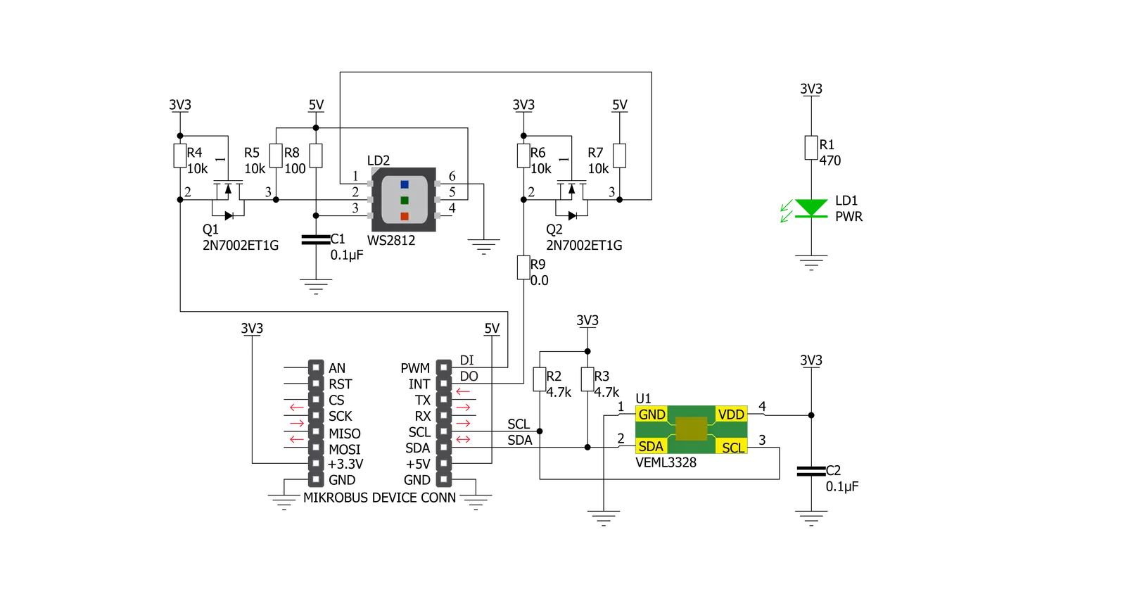
Color 10 Click is based on VEML3328, a RGB and IR light sensor from Vishay Semiconducotr. This sensor is a 16-bit, low power, high sensitivity CMOS color sensor and signal conditioning IC, that can be operated via a simple I2C commands. This sensor has many features that make it a perfect solution for small designs such as the Color 10 Click board™. One of these features is certainly its high level of integration that allows a minimal number of external components. VEML3328 provides excellent temperature compensation capability for keeping the output stable under changing temperature. The sensor’s functions are
easily operated via the simple command format of I2C (SMBus compatible) interface protocol. VEML3328 has a low operating voltage range of 2.6V to 3.6V, integrated modules, color sensor and signal conditioning IC, supports low transmittance (dark) lens design and provides 16-bit resolution for each channel (R, G, B, C, and IR). The WS2812 on Color 10 Click board™ can be used for testing purposes as well as the light source for object color detector, since VEML3328 can detect the color which WS2812 emits in R, G, B range. For clear and IR light, appropriate photodiodes should be used. The WS2812 can be controlled by data
protocol on DI and DO pins, data transfer protocol use single NZR communication mode. After the pixel power-on reset, the DI port receive data from microcontroller, the first pixel collect initial 24bit data then sent to the internal data latch, the other data which reshaping by the internal signal reshaping amplification circuit sent to the next cascade pixel through the DO port. After transmission for each pixel, the signal to reduce 24bit pixel adopt auto reshaping transmit technology, making the pixel cascade number is not limited the signal transmission, only depend on the speed of signal transmission.


Features overview
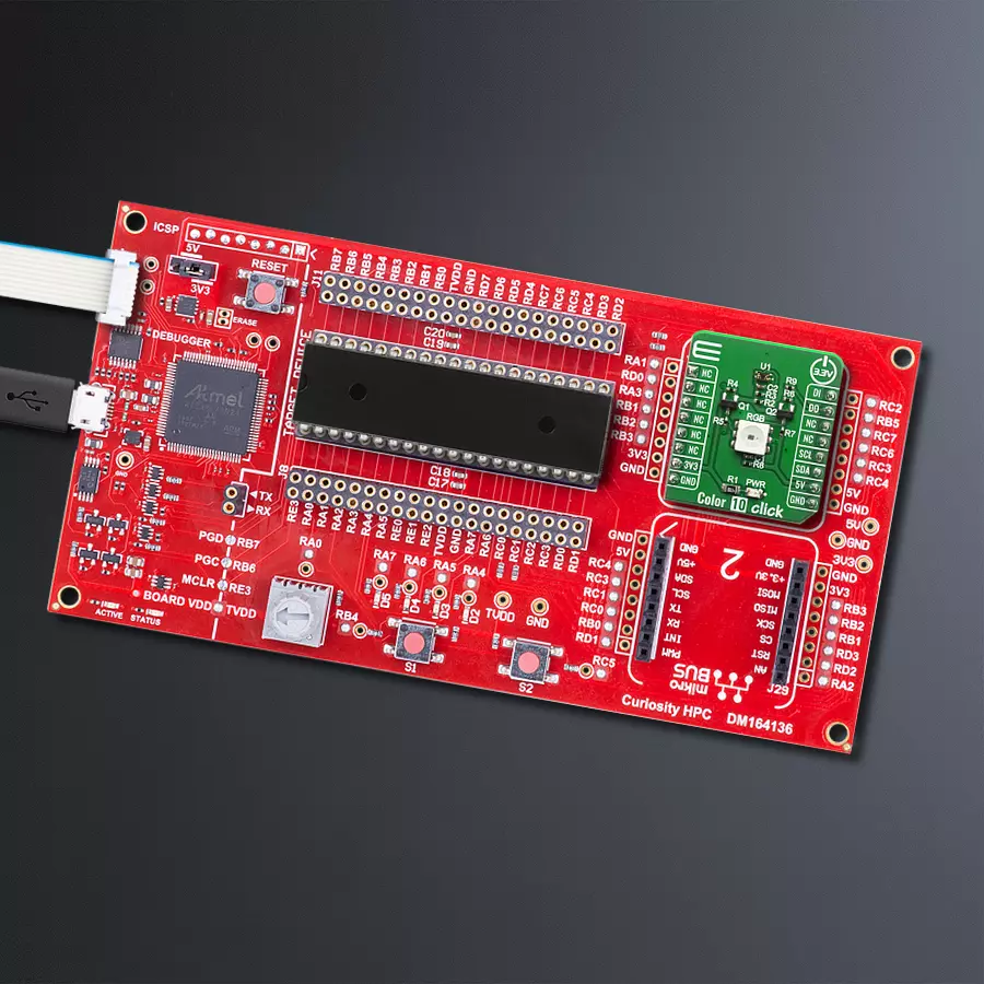
Development board
Curiosity HPC, standing for Curiosity High Pin Count (HPC) development board, supports 28- and 40-pin 8-bit PIC MCUs specially designed by Microchip for the needs of rapid development of embedded applications. This board has two unique PDIP sockets, surrounded by dual-row expansion headers, allowing connectivity to all pins on the populated PIC MCUs. It also contains a powerful onboard PICkit™ (PKOB), eliminating the need for an external programming/debugging tool, two mikroBUS™ sockets for Click board™ connectivity, a USB connector, a set of indicator LEDs, push button switches and a variable potentiometer. All
these features allow you to combine the strength of Microchip and Mikroe and create custom electronic solutions more efficiently than ever. Each part of the Curiosity HPC development board contains the components necessary for the most efficient operation of the same board. An integrated onboard PICkit™ (PKOB) allows low-voltage programming and in-circuit debugging for all supported devices. When used with the MPLAB® X Integrated Development Environment (IDE, version 3.0 or higher) or MPLAB® Xpress IDE, in-circuit debugging allows users to run, modify, and troubleshoot their custom software and hardware
quickly without the need for additional debugging tools. Besides, it includes a clean and regulated power supply block for the development board via the USB Micro-B connector, alongside all communication methods that mikroBUS™ itself supports. Curiosity HPC development board allows you to create a new application in just a few steps. Natively supported by Microchip software tools, it covers many aspects of prototyping thanks to many number of different Click boards™ (over a thousand boards), the number of which is growing daily.

Microcontroller Overview
MCU Card / MCU
Architecture
PIC
MCU Memory (KB)
32
Silicon Vendor
Microchip
Pin count
40
RAM (Bytes)
2048
Used MCU Pins
mikroBUS™ mapper
Take a closer look
Click board™ Schematic
Step by step
Project assembly

Start by selecting your development board and Click board™. Begin with the Curiosity HPC as your development board.


Software Support
Library Description
This library contains API for Color 10 Click driver.
Key functions:
color10_generic_read- This function reads data from the desired registercolor10_get_color_value- This function calculates the color valuecolor10_get_color- This function identifies the color using the color value.
Open Source
Code example
The complete application code and a ready-to-use project are available through the NECTO Studio Package Manager for direct installation in the NECTO Studio. The application code can also be found on the MIKROE GitHub account.
/*!
 * \file
 * \brief Color10 Click example
 *
 * # Description
 * Color 10 Click is carrying a sensor for RGB and IR light sensing as well as
 * the RGB diode incorporated on the board which makes it good color detection
 * device when its combined with a white LED.
 *
 * The demo application is composed of two sections :
 *
 * ## Application Init
 * Initialize I2C driver.
 *
 * ## Application Task
 * This example senses orange, red, pink, purple, blue, cyan, green or yellow color
 * and IR light and print it via UART terminal.
 *
 *
 * \author MikroE Team
 *
 */
// ------------------------------------------------------------------- INCLUDES

#include "board.h"
#include "log.h"
#include "color10.h"

// ------------------------------------------------------------------ VARIABLES

static color10_t color10;
static log_t logger;

// ------------------------------------------------------- ADDITIONAL FUNCTIONS

void write_color ( void )
{
    float color_val;
    uint8_t color;

    color_val = color10_get_color_value( &color10 );
    color = color10_get_color( color_val );

    switch ( color )
    {
        case COLOR10_COLOR_ORANGE:
        {
            log_printf( &logger, "ORANGE" );
        break;
        }

        case COLOR10_COLOR_RED:
        {
            log_printf( &logger, "RED" );
        break;
        }

        case COLOR10_COLOR_PINK:
        {
            log_printf( &logger, "PINK" );
        break;
        }

        case COLOR10_COLOR_PURPLE:
        {
            log_printf( &logger, "PURPLE" );
        break;
        }

        case COLOR10_COLOR_BLUE:
        {
            log_printf( &logger, "BLUE" );
        break;
        }

        case COLOR10_COLOR_CYAN:
        {
            log_printf( &logger, "CYAN" );
        break;
        }

        case COLOR10_COLOR_GREEN:
        {
            log_printf( &logger, "GREEN" );
        break;
        }

        case COLOR10_COLOR_YELLOW:
        {
            log_printf( &logger, "YELLOW" );
        break;
        }

        default:
        {
            log_printf( &logger, "NOT DEFINED" );
        break;
        }
    }
}

// ------------------------------------------------------ APPLICATION FUNCTIONS

void application_init ( void )
{
    log_cfg_t log_cfg;
    color10_cfg_t cfg;
    uint8_t id_data;

    /**
     * Logger initialization.
     * Default baud rate: 115200
     * Default log level: LOG_LEVEL_DEBUG
     * @note If USB_UART_RX and USB_UART_TX
     * are defined as HAL_PIN_NC, you will
     * need to define them manually for log to work.
     * See @b LOG_MAP_USB_UART macro definition for detailed explanation.
     */
    LOG_MAP_USB_UART( log_cfg );
    log_init( &logger, &log_cfg );
    log_info( &logger, "---- Application Init ----" );

    //  Click initialization.

    color10_cfg_setup( &cfg );
    COLOR10_MAP_MIKROBUS( cfg, MIKROBUS_1 );
    color10_init( &color10, &cfg );
    Delay_ms ( 500 );

    if ( color10_get_id( &color10 ) == COLOR10_DEVICE_ID )
    {
         log_printf( &logger, " -DEVICE ID OK\r\n" );
    }
    else
    {
        log_printf( &logger, " -DEVICE ID ERROR\r\n" );
        for( ; ; );
    }

    color10_config( &color10, COLOR10_CFG_HIGH_DYNAMIC_RANGE_1 |
                    COLOR10_CFG_INTEGRATION_TIME_SETT_50_MS |
                    COLOR10_CFG_AUTO_MODE |
                    COLOR10_CFG_TRIGGER_NO |
                    COLOR10_CFG_POWER_ON |
                    COLOR10_CFG_GAIN_1_X1 |
                    COLOR10_CFG_GAIN_2_X1 );
    log_printf( &logger, "-----Init done------\r\n" );
    Delay_ms ( 500 );
}

void application_task ( void )
{
    uint16_t read_data;
    float color_data;

    read_data = color10_generic_read ( &color10, COLOR10_CMD_REG_IR );
    log_printf( &logger, " -IR value: %d\r\n", read_data );
    log_printf( &logger, " -Color: " );
    write_color( );

    log_printf( &logger, " ********************** \r\n" );
    Delay_ms ( 1000 );
}

int main ( void )
{
    /* Do not remove this line or clock might not be set correctly. */
    #ifdef PREINIT_SUPPORTED
    preinit();
    #endif

    application_init( );

    for ( ; ; )
    {
        application_task( );
    }

    return 0;
}


// ------------------------------------------------------------------------ END
Additional Support
Resources
Category:Optical


