Harness the precision of Hall-effect current sensing using CQ3300 and PIC32MZ2048EFH100
Smart solution with advanced current sensing

Published Aug 12, 2023
Click board™
Hall Current 9 Click
Dev. board
Flip&Click PIC32MZ
Compiler
NECTO Studio
MCU
PIC32MZ2048EFH100
Experience enhanced reliability with our Hall-effect current sensing technology, which offers precise measurements even in challenging environments
A
A
Hardware Overview
How does it work?
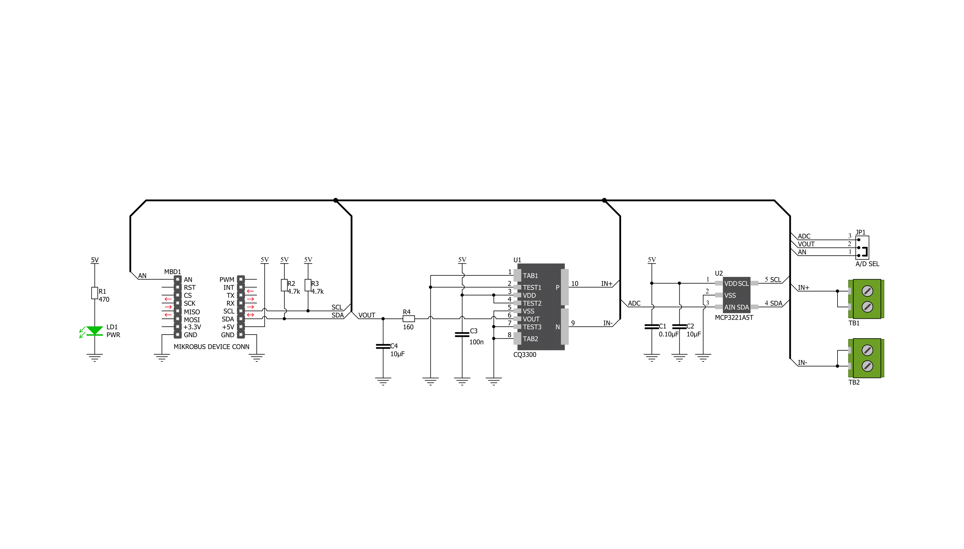
Hall Current 9 Click is based on the CQ3300, a high-speed response coreless current sensor using a Hall sensor that outputs the analog voltage proportional to the AC/DC from AKM Semiconductor. This current sensor has small-size and high galvanic isolation, specially designed for the current range from -6.4A to +6.4A. Quantum well ultra-thin film of Indium Arsenide is used as the Hall sensor, enabling high-accuracy and high-speed current sensing showing good performance in small-sized inverter applications. It has primary conductor resistance that significantly reduces the heat generated by current compared to a shunt resistor, allowing a continuous current flow of 20Arms. It has an ultra-fast high response of 0.5μs, making it suitable for overcurrent applications. The internal structure of the CQ3300 consists of several blocks such as a primary conductor, Hall sensor, amplifier, buffer, compensation block, bias, and
EEPROM unit. The primary conductor measures the applied current, while the Hall element detects magnetic flux density generated from the measured current. Hall element’s output is then amplified, with a compensation circuit that adjusts the temperature drifts of sensitivity and zero-current output voltage. The last block is the output buffer with gain that outputs the voltage proportional to the current applied to the primary conductor. The CQ3300 has a ratiometric output, which changes proportionally to the supply voltage. It is suitable for applications where the analog output is converted to digital using an A/D converter and where the power supply voltage fluctuation causes reference error of the A/D converter. Just like that, the output voltage can be converted to a digital value using MCP3221, a successive approximation A/D converter with a 12-bit resolution from Microchip, using a 2-wire I2C compatible interface, or can be
sent directly to an analog pin of the mikroBUS™ socket labeled as AN. Selection can be performed by onboard SMD jumper labeled as A/D SEL to an appropriate position marked as AN and ADC. The MCP3221 provides one single-ended input with low power consumption, a low maximum conversion current, and a Standby current of 250 μA and 1 μA, respectively. Data can be transferred at 100kbit/s in the Standard and 400kbit/s in the Fast Mode. Also, maximum sample rates of 22.3 kSPS with the MCP3221 are possible in a Continuous-Conversion Mode with a clock rate of 400 kHz. This Click board™ can be operated only with a 5V logic voltage level. The board must perform appropriate logic voltage level conversion before using MCUs with different logic levels. Also, it comes equipped with a library containing functions and an example code that can be used, as a reference, for further development.


Features overview
Development board
Flip&Click PIC32MZ is a compact development board designed as a complete solution that brings the flexibility of add-on Click boards™ to your favorite microcontroller, making it a perfect starter kit for implementing your ideas. It comes with an onboard 32-bit PIC32MZ microcontroller, the PIC32MZ2048EFH100 from Microchip, four mikroBUS™ sockets for Click board™ connectivity, two USB connectors, LED indicators, buttons, debugger/programmer connectors, and two headers compatible with Arduino-UNO pinout. Thanks to innovative manufacturing technology,
it allows you to build gadgets with unique functionalities and features quickly. Each part of the Flip&Click PIC32MZ development kit contains the components necessary for the most efficient operation of the same board. In addition, there is the possibility of choosing the Flip&Click PIC32MZ programming method, using the chipKIT bootloader (Arduino-style development environment) or our USB HID bootloader using mikroC, mikroBasic, and mikroPascal for PIC32. This kit includes a clean and regulated power supply block through the USB Type-C (USB-C) connector. All communication
methods that mikroBUS™ itself supports are on this board, including the well-established mikroBUS™ socket, user-configurable buttons, and LED indicators. Flip&Click PIC32MZ development kit allows you to create a new application in minutes. Natively supported by Mikroe software tools, it covers many aspects of prototyping thanks to a considerable number of different Click boards™ (over a thousand boards), the number of which is growing every day.

Microcontroller Overview
MCU Card / MCU

Architecture
PIC32
MCU Memory (KB)
2048
Silicon Vendor
Microchip
Pin count
100
RAM (Bytes)
524288
Used MCU Pins
mikroBUS™ mapper
Take a closer look
Click board™ Schematic
Step by step
Project assembly

Start by selecting your development board and Click board™. Begin with the Flip&Click PIC32MZ as your development board.


Software Support
Library Description
This library contains API for Hall Current 9 Click driver.
Key functions:
hallcurrent9_read_adc- Hall Current 9 I2C ADC reading functionhallcurrent9_set_calibration- Hall Current 9 set calibration functionhallcurrent9_get_current- Hall Current 9 get current function
Open Source
Code example
The complete application code and a ready-to-use project are available through the NECTO Studio Package Manager for direct installation in the NECTO Studio. The application code can also be found on the MIKROE GitHub account.
/*!
 * @file main.c
 * @brief HallCurrent9 Click example
 *
 * # Description
 * This library contains API for Hall Current 9 Click driver.
 * The library contains drivers for measuring ADC values
 * and for calculation current.
 *
 * The demo application is composed of two sections :
 *
 * ## Application Init
 * Initializes I2C driver and triggers the built-in calibration.
 *
 * ## Application Task
 * This is an example that demonstrates the use of the Hall Current 9 Click board.
 * In this example, we read and display the ADC and current ( mA ) data.
 * Results are being sent to the Usart Terminal where you can track their changes.
 *
 * @author Nenad Filipovic
 *
 */

#include "board.h"
#include "log.h"
#include "hallcurrent9.h"

static hallcurrent9_t hallcurrent9;
static log_t logger;

static uint16_t adc_data;
static float current;
hallcurrent9_calibration_data_t avg_adc_data;

void application_init ( void ) {
    log_cfg_t log_cfg;                    /**< Logger config object. */
    hallcurrent9_cfg_t hallcurrent9_cfg;  /**< Click config object.  */

    /**
     * Logger initialization.
     * Default baud rate: 115200
     * Default log level: LOG_LEVEL_DEBUG
     * @note If USB_UART_RX and USB_UART_TX
     * are defined as HAL_PIN_NC, you will
     * need to define them manually for log to work.
     * See @b LOG_MAP_USB_UART macro definition for detailed explanation.
     */
    LOG_MAP_USB_UART( log_cfg );
    log_init( &logger, &log_cfg );
    log_printf( &logger, "\r\n" );
    log_printf( &logger, "--------------------------\r\n" );
    log_printf( &logger, "   Hall Current 9 Click   \r\n" );
    log_printf( &logger, "--------------------------\r\n" );
    log_info( &logger, " Application Init " );

    // Click initialization.

    hallcurrent9_cfg_setup( &hallcurrent9_cfg );
    HALLCURRENT9_MAP_MIKROBUS( hallcurrent9_cfg, MIKROBUS_1 );
    err_t init_flag = hallcurrent9_init( &hallcurrent9, &hallcurrent9_cfg );
    if ( init_flag == I2C_MASTER_ERROR ) {
        log_error( &logger, " Application Init Error. " );
        log_info( &logger, " Please, run program again... " );

        for ( ; ; );
    }

    log_printf( &logger, "---------------------------\r\n" );
    log_printf( &logger, "        Calibration        \r\n" );
    log_printf( &logger, "- - - - - - - - - - - - - -\r\n" );
    log_printf( &logger, "> Turn OFF the Power unit <\r\n" );
    log_printf( &logger, "- - - - - - - - - - - - - -\r\n" );
    log_printf( &logger, "  In the following 5 sec.  \r\n" );
    log_printf( &logger, " turn OFF the Power Supply \r\n" );
    Delay_ms ( 1000 );
    Delay_ms ( 1000 );
    Delay_ms ( 1000 );
    Delay_ms ( 1000 );
    Delay_ms ( 1000 );

    log_printf( &logger, "-------------------------\r\n" );
    log_printf( &logger, "    Start calibration    \r\n" );

    if ( hallcurrent9_set_calibration( &hallcurrent9, &avg_adc_data ) == HALLCURRENT9_OK ) {
        log_printf( &logger, "---------------------------\r\n" );
        log_printf( &logger, "    Calibration  Done    \r\n" );
        Delay_ms ( 1000 );
    }

    log_printf( &logger, "---------------------------\r\n" );
    log_printf( &logger, "    Start measurements :   \r\n" );
    log_printf( &logger, "---------------------------\r\n" );
}

void application_task ( void ) {
    log_printf( &logger, "--------------------------\r\n", adc_data );
    hallcurrent9_read_adc( &hallcurrent9, &adc_data );
    log_printf( &logger, "   ADC     : %d \r\n", adc_data );

    current = hallcurrent9_get_current( &hallcurrent9, &avg_adc_data );
    log_printf( &logger, "   Current : %.2f mA \r\n", current );
    Delay_ms ( 1000 );
    Delay_ms ( 1000 );
}

int main ( void )
{
    /* Do not remove this line or clock might not be set correctly. */
    #ifdef PREINIT_SUPPORTED
    preinit();
    #endif

    application_init( );

    for ( ; ; )
    {
        application_task( );
    }

    return 0;
}

// ------------------------------------------------------------------------ END
Additional Support
Resources
Category:Current sensor


