Provide accurate and high-speed current sensing with CZ3AG2 and STM32F031K6
Coreless current sensor based on Hall sensor technology

Published Oct 01, 2024
Click board™
Hall Current 19 Click
Dev. board
Nucleo 32 with STM32F031K6 MCU
Compiler
NECTO Studio
MCU
STM32F031K6
Monitor current flow without physically interrupting the circuit
A
A
Hardware Overview
How does it work?
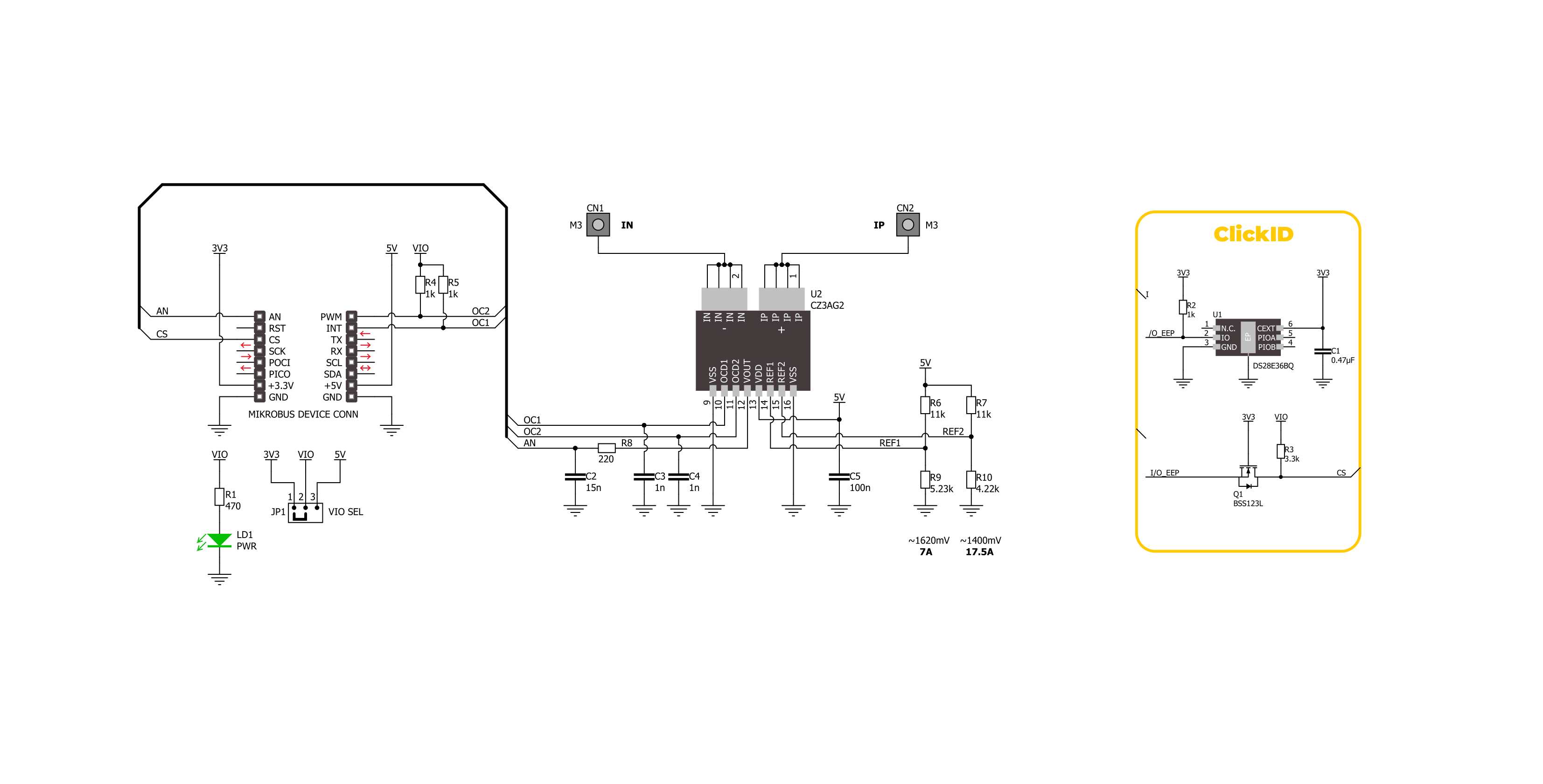
Hall Current 19 Click is based on the CZ3AG2, a coreless current sensor from AKM Semiconductor. This sensor uses Hall sensor technology to provide an analog voltage output proportional to the AC/DC current on the AN pin of the mikroBUS™ socket. Using a Group III-V semiconductor thin film as the Hall element, the CZ3AG2 ensures high-accuracy and high-speed current sensing. It also includes functions for reducing stray magnetic fields and dual overcurrent detection. Being UL 61800-5-1
safety compliant, the CZ3AG2-based Hall Current 19 Click is perfect for industrial AC drives, servo motors, UPS systems, general inverters, and power conditioners. As mentioned, this Click board™ is equipped with dual overcurrent detection capabilities on the OC1 and OC2 pins of the mikroBUS™ socket. Using voltage dividers R6/R9 and R7/R10, it sets precise current limits ranging from 7A to 17.5A. This ensures that any current value falling outside this specified range will be
promptly detected by the overcurrent detectors, providing reliable protection and accurate measurement. This Click board™ can operate with either 3.3V or 5V logic voltage levels selected via the VIO SEL jumper. This way, both 3.3V and 5V capable MCUs can use the communication lines properly. Also, this Click board™ comes equipped with a library containing easy-to-use functions and an example code that can be used as a reference for further development.

Features overview
Development board
Nucleo 32 with STM32F031K6 MCU board provides an affordable and flexible platform for experimenting with STM32 microcontrollers in 32-pin packages. Featuring Arduino™ Nano connectivity, it allows easy expansion with specialized shields, while being mbed-enabled for seamless integration with online resources. The
board includes an on-board ST-LINK/V2-1 debugger/programmer, supporting USB reenumeration with three interfaces: Virtual Com port, mass storage, and debug port. It offers a flexible power supply through either USB VBUS or an external source. Additionally, it includes three LEDs (LD1 for USB communication, LD2 for power,
and LD3 as a user LED) and a reset push button. The STM32 Nucleo-32 board is supported by various Integrated Development Environments (IDEs) such as IAR™, Keil®, and GCC-based IDEs like AC6 SW4STM32, making it a versatile tool for developers.

Microcontroller Overview
MCU Card / MCU

Architecture
ARM Cortex-M0
MCU Memory (KB)
32
Silicon Vendor
STMicroelectronics
Pin count
32
RAM (Bytes)
4096
You complete me!
Accessories
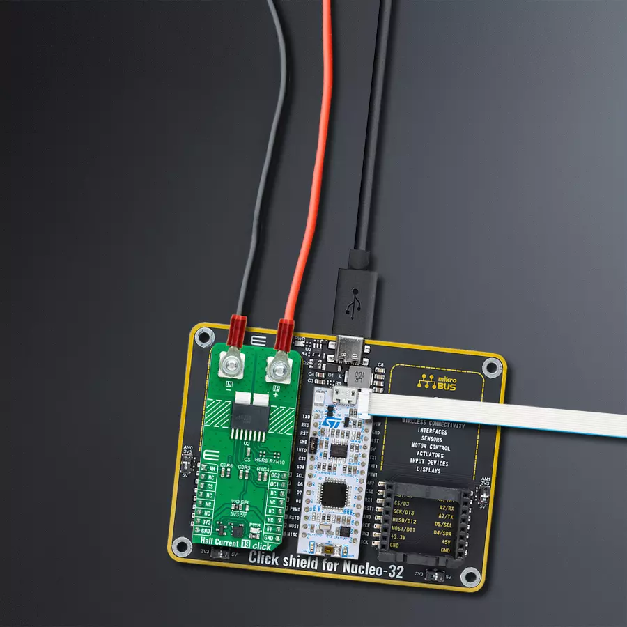
Click Shield for Nucleo-32 is the perfect way to expand your development board's functionalities with STM32 Nucleo-32 pinout. The Click Shield for Nucleo-32 provides two mikroBUS™ sockets to add any functionality from our ever-growing range of Click boards™. We are fully stocked with everything, from sensors and WiFi transceivers to motor control and audio amplifiers. The Click Shield for Nucleo-32 is compatible with the STM32 Nucleo-32 board, providing an affordable and flexible way for users to try out new ideas and quickly create prototypes with any STM32 microcontrollers, choosing from the various combinations of performance, power consumption, and features. The STM32 Nucleo-32 boards do not require any separate probe as they integrate the ST-LINK/V2-1 debugger/programmer and come with the STM32 comprehensive software HAL library and various packaged software examples. This development platform provides users with an effortless and common way to combine the STM32 Nucleo-32 footprint compatible board with their favorite Click boards™ in their upcoming projects.

Used MCU Pins
mikroBUS™ mapper
Take a closer look
Click board™ Schematic
Step by step
Project assembly

Start by selecting your development board and Click board™. Begin with the Nucleo 32 with STM32F031K6 MCU as your development board.


Software Support
Library Description
This library contains API for Hall Current 19 Click driver.
Key functions:
hallcurrent19_get_oc2- This function is used to get state of the overcurrent 2 detection of the Hall Current 19 Clickhallcurrent19_set_zero_ref- This function sets the zero voltage reference of the Hall Current 19 Clickhallcurrent19_get_current- This function reads and calculate input current value of the Hall Current 19 Click
Open Source
Code example
The complete application code and a ready-to-use project are available through the NECTO Studio Package Manager for direct installation in the NECTO Studio. The application code can also be found on the MIKROE GitHub account.
/*!
 * @file main.c
 * @brief Hall Current 19 Click Example.
 *
 * # Description
 * This example demonstrates the use of Hall Current 19 Click board
 * by reading and displaying the current measurements.
 *
 * The demo application is composed of two sections :
 *
 * ## Application Init
 * Initializes the driver and logger, and set the zero voltage reference.
 *
 * ## Application Task
 * The demo application reads the current measurements [A] and displays the results.
 * Results are being sent to the UART Terminal, where you can track their changes.
 *
 * @author Stefan Ilic
 *
 */

#include "board.h"
#include "log.h"
#include "hallcurrent19.h"

static hallcurrent19_t hallcurrent19;   /**< Hall Current 19 Click driver object. */
static log_t logger;    /**< Logger object. */

void application_init ( void )
{
    log_cfg_t log_cfg;  /**< Logger config object. */
    hallcurrent19_cfg_t hallcurrent19_cfg;  /**< Click config object. */

    /**
     * Logger initialization.
     * Default baud rate: 115200
     * Default log level: LOG_LEVEL_DEBUG
     * @note If USB_UART_RX and USB_UART_TX
     * are defined as HAL_PIN_NC, you will
     * need to define them manually for log to work.
     * See @b LOG_MAP_USB_UART macro definition for detailed explanation.
     */
    LOG_MAP_USB_UART( log_cfg );
    log_init( &logger, &log_cfg );
    log_info( &logger, " Application Init " );

    // Click initialization.
    hallcurrent19_cfg_setup( &hallcurrent19_cfg );
    HALLCURRENT19_MAP_MIKROBUS( hallcurrent19_cfg, MIKROBUS_1 );
    if ( ADC_ERROR == hallcurrent19_init( &hallcurrent19, &hallcurrent19_cfg ) )
    {
        log_error( &logger, " Communication init." );
        for ( ; ; );
    }

    log_printf( &logger, " Turn off the load current in the following 5 sec.\r\n" );
    Delay_ms ( 1000 );
    Delay_ms ( 1000 );
    Delay_ms ( 1000 );
    Delay_ms ( 1000 );
    Delay_ms ( 1000 );
    if ( HALLCURRENT19_OK == hallcurrent19_set_zero_ref( &hallcurrent19 ) )
    {
        log_printf( &logger, " Process complete!\r\n");
    }
    else
    {
        log_error( &logger, " Zero reference." );
        for ( ; ; );
    }

    log_info( &logger, " Application Task " );
}

void application_task ( void )
{
    float voltage = 0;
    if ( HALLCURRENT19_OK == hallcurrent19_get_current ( &hallcurrent19, &voltage ) )
    {
        log_printf( &logger, " Current : %.3f[A]\r\n\n", voltage );
        Delay_ms ( 1000 );
    }
    if ( HALLCURRENT19_OCD_ACTIVE == hallcurrent19_get_oc1( &hallcurrent19 ) )
    {
        log_printf( &logger, " Current over 7A \r\n" );
    }
    if ( HALLCURRENT19_OCD_ACTIVE == hallcurrent19_get_oc2( &hallcurrent19 ) )
    {
        log_printf( &logger, " Current over 17.5A \r\n" );
    }
}

int main ( void )
{
    /* Do not remove this line or clock might not be set correctly. */
    #ifdef PREINIT_SUPPORTED
    preinit();
    #endif

    application_init( );

    for ( ; ; )
    {
        application_task( );
    }

    return 0;
}

// ------------------------------------------------------------------------ END
Additional Support
Resources
Category:Current sensor


