Achieve versatility in motor control with STSPIN250 and PIC32MZ2048EFH100
Unleash the power of brushed DC motor control!

Published Jul 24, 2023
Click board™
STSPIN250 Click
Dev. board
Flip&Click PIC32MZ
Compiler
NECTO Studio
MCU
PIC32MZ2048EFH100
Experience enhanced motor performance with our brushed DC motor driver, optimizing efficiency, reducing wear, and extending the operational lifespan of your motors
A
A
Hardware Overview
How does it work?
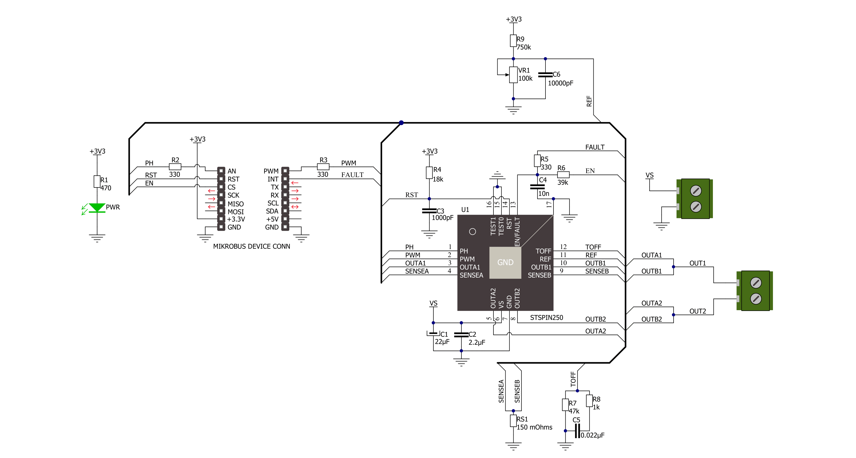
STSPIN250 Click is based on the STSPIN250, a low voltage DC brushed motor driver by STMicroelectronics. This device integrates two full-bridge MOSFET channels in a parallel configuration, sustaining up to 2.6A. This IC targets battery-powered applications, featuring optimizations toward lowered power consumption. It has a PWM current controller with a fixed OFF time, during which the current decay sequence is performed. This effectively limits the current through the connected load (motor). The OFF (decay) time is approximately 40 µs on this Click board™. The PWM current controller compares the voltage across the sense resistor (VSENS) and the VREF voltage, which is adjustable on STSPIN250 click. When VSENS exceeds the VREF voltage, the current limiting is triggered, and the OFF timer starts counting. The decay sequence is performed. Knowing the RSENS, it can be easily calculated how much voltage should be applied to the REF pin of the STSPIN250 to limit the current according to ILOAD. For example, if 0.388V is applied at the VREF pin, the current limit will be maxed out to 2.58A. The onboard
potentiometer allows you to adjust the VREF voltage according to needs simply. The connected motor can be controlled by using these pins: PWM, PH, RST, and EN/INT. The PH pin determines the direction of the current. If set to a HIGH logic level, the current will flow in one direction, and vice-versa: when a LOW logic level is applied, the current will reverse its direction. This pin is routed to the AN pin of the mikroBUS™ and labeled as PH. PWM pin can be used to regulate the speed of the rotation. When this pin has a LOW logic level, the current will start circulating through the low-side (LS) MOSFETs and the motor coil. When there is a HIGH logic level on this pin, the current will flow through the load, depending on the logic state of the PH pin. A higher duty cycle percentage will result in higher angular speed. While the current decay sequence is performed, the logic states on the input pins will be disregarded until the decay timer expires. The decay time is fixed to approximately 40 µs on this Click board™. The STBY/RESET (RST) pin of the STSPIN250 is used to set both bridge outputs in HIGH-Z mode, disconnecting the power supply
from the output stage. This pin allows lower average power consumption as no current can flow from the power supply to the motor. This pin is routed to the RST pin of the mikroBUS™. The EN/FAULT (EN) pin has a double purpose: when set to a high logic level, it acts as a chip enable, allowing the device to operate. In the case of a fault condition on the IC, it will be asserted to a LOW logic level, acting as an interrupt pin. A restart attempt will be made after a timeout period defined by the external capacitor and resistor values. This pin is routed to the CS and INT pin of the mikroBUS™, allowing the host MCU to use both functions. These pins are labeled EN and FLT on the Click board™, respectively. The motor power supply can be connected to the input terminal labeled as VIN and should be within the range of 1.8V to 10V. The motor can be connected at the second terminal, between two poles labeled as A+ and A-. The Click board™ requires an external power supply for the motor to work. However, it also requires 3.3V from the mikroBUS™ rail.

Features overview
Development board
Flip&Click PIC32MZ is a compact development board designed as a complete solution that brings the flexibility of add-on Click boards™ to your favorite microcontroller, making it a perfect starter kit for implementing your ideas. It comes with an onboard 32-bit PIC32MZ microcontroller, the PIC32MZ2048EFH100 from Microchip, four mikroBUS™ sockets for Click board™ connectivity, two USB connectors, LED indicators, buttons, debugger/programmer connectors, and two headers compatible with Arduino-UNO pinout. Thanks to innovative manufacturing technology,
it allows you to build gadgets with unique functionalities and features quickly. Each part of the Flip&Click PIC32MZ development kit contains the components necessary for the most efficient operation of the same board. In addition, there is the possibility of choosing the Flip&Click PIC32MZ programming method, using the chipKIT bootloader (Arduino-style development environment) or our USB HID bootloader using mikroC, mikroBasic, and mikroPascal for PIC32. This kit includes a clean and regulated power supply block through the USB Type-C (USB-C) connector. All communication
methods that mikroBUS™ itself supports are on this board, including the well-established mikroBUS™ socket, user-configurable buttons, and LED indicators. Flip&Click PIC32MZ development kit allows you to create a new application in minutes. Natively supported by Mikroe software tools, it covers many aspects of prototyping thanks to a considerable number of different Click boards™ (over a thousand boards), the number of which is growing every day.

Microcontroller Overview
MCU Card / MCU

Architecture
PIC32
MCU Memory (KB)
2048
Silicon Vendor
Microchip
Pin count
100
RAM (Bytes)
524288
Used MCU Pins
mikroBUS™ mapper
Take a closer look
Click board™ Schematic
Step by step
Project assembly

Start by selecting your development board and Click board™. Begin with the Flip&Click PIC32MZ as your development board.


Software Support
Library Description
This library contains API for STSPIN250 Click driver.
Key functions:
stspin250_set_ph- This function regulates Direction control pin state. It controls direction of the currentstspin250_enable- This function regulates enable pin statestspin250_reset- This function regulates reset pin state
Open Source
Code example
The complete application code and a ready-to-use project are available through the NECTO Studio Package Manager for direct installation in the NECTO Studio. The application code can also be found on the MIKROE GitHub account.
/*!
 * @file
 * @brief Stspin250 Click example
 *
 * # Description
 * This application enables usage of brushed DC motor driver with
 * the current limiting and current sensing.
 *
 * The demo application is composed of two sections :
 *
 * ## Application Init
 * Initialization driver init, PWM init and enable device
 *
 * ## Application Task
 * This is a example which demonstrates the use of Stspin250 Click board.
 * Stspin250 Click communicates with register via PWM interface.
 * It shows moving in the left direction from slow to fast speed
 * and from fast to slow speed.
 * Results are being sent to the Usart Terminal where you can track their changes.
 *
 * @author Nikola Peric
 *
 */
// ------------------------------------------------------------------- INCLUDES

#include "board.h"
#include "log.h"
#include "stspin250.h"

// ------------------------------------------------------------------ VARIABLES

static stspin250_t stspin250;
static log_t logger;
uint8_t motor_direction = 1;

// ------------------------------------------------------ APPLICATION FUNCTIONS

void application_init ( void )
{
    log_cfg_t log_cfg;
    stspin250_cfg_t cfg;

    /**
     * Logger initialization.
     * Default baud rate: 115200
     * Default log level: LOG_LEVEL_DEBUG
     * @note If USB_UART_RX and USB_UART_TX
     * are defined as HAL_PIN_NC, you will
     * need to define them manually for log to work.
     * See @b LOG_MAP_USB_UART macro definition for detailed explanation.
     */
    LOG_MAP_USB_UART( log_cfg );
    log_init( &logger, &log_cfg );
    log_info( &logger, "---- Application Init ----" );

    //  Click initialization.

    stspin250_cfg_setup( &cfg );
    STSPIN250_MAP_MIKROBUS( cfg, MIKROBUS_1 );
    stspin250_init( &stspin250, &cfg );

    stspin250_enable( &stspin250, STSPIN250_DEVICE_ENABLE );
    stspin250_set_duty_cycle ( &stspin250, 0.0 );

    stspin250_pwm_start( &stspin250 );
    log_info( &logger, "---- Application Task ----" );
    Delay_ms ( 500 );
}

void application_task ( void )
{
    static int8_t duty_cnt = 1;
    static int8_t duty_inc = 1;
    float duty = duty_cnt / 10.0;

    if ( motor_direction == 1 )
    {
        stspin250_set_ph( &stspin250, 1 );
        log_printf( &logger, "> CLOCKWISE <\r\n" );
    }
    else
    {
        stspin250_set_ph( &stspin250, 0 );
        log_printf( &logger, "> COUNTER CLOCKWISE <\r\n" );
    }

    stspin250_set_duty_cycle ( &stspin250, duty );
    log_printf( &logger, "Duty: %d%%\r\n", ( uint16_t )( duty_cnt * 10 ) );
    Delay_ms ( 500 );

    if ( 10 == duty_cnt )
    {
        duty_inc = -1;
    }
    else if ( 0 == duty_cnt )
    {
        duty_inc = 1;
        if ( motor_direction == 1 )
        {
            motor_direction = 0;
        }
        else if ( motor_direction == 0 )
        {
            motor_direction = 1;
        }
    }
    duty_cnt += duty_inc;
}

int main ( void )
{
    /* Do not remove this line or clock might not be set correctly. */
    #ifdef PREINIT_SUPPORTED
    preinit();
    #endif

    application_init( );

    for ( ; ; )
    {
        application_task( );
    }

    return 0;
}


// ------------------------------------------------------------------------ END
Additional Support
Resources
Category:Brushed


