Ensure reliable and consistent movement data in your motion tracking and control systems with TCUT1800X01 and PIC32MZ2048EFH100
A new era in rotation encoding

Published Sep 23, 2023
Click board™
Opto Encoder 3 Click
Dev. board
Flip&Click PIC32MZ
Compiler
NECTO Studio
MCU
PIC32MZ2048EFH100
Experience the benefits of real-time, high-resolution motion feedback
A
A
Hardware Overview
How does it work?
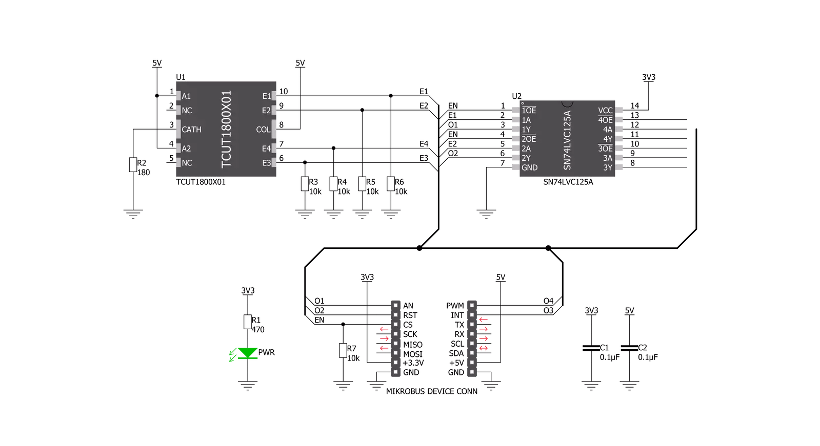
Opto Encoder 3 Click is based on the TCUT1800X01, a tall dome quad channel transmissive optical sensor with phototransistor outputs from Vishay Semiconductor. This sensor is equipped with one infrared LED with the wavelength of 950nm, and four phototransistors. These phototransistors are positioned behind small slits on the sensor, on the opposite side of the LED. They form four separate channels. When the transistors get illuminated by the LED, they become conductive. The collectors of these transistors are connected to the same pin, while their emitters are routed to separate output pins of the TCUT1800X01 - E1, E2 E3, and E4. This allows the activity on each channel to be detected by the host MCU separately. Since the signals of these output channels are not enough to drive pins on a
host MCU, the Click board™ features two additional buffer IC – the SN74LVC125A, from texas instruments. E1, E2, E3, and E4 pins are routed to the input pins od the buffer IC. These pins are pulled to a LOW logic level by the pull-down resistors, to avoid floating. The output pins of the buffer are routed to the mikroBUS™ AN, RST, INT, and PWM pins respectively. Signal encoding itself is done by the host MCU. Having four optical sensing channels, Opto Encoder 3 click has the ability of both speed and direction encoding. The most common usage is encoding of the step motor position: a cylinder with slits is physically mounted above the sensor so that the LED can illuminate the phototransistors only through these slits. By rotating this cylinder, the light beam will be blocked periodically. The single sensor output
will be a pulse train, while the cylinder is rotating. Having two photo sensors physically distanced by a small amount, allows the pulse signal of the first sensor to be either delayed or expedited with respect to the pulse on the second sensor, depending on the rotational direction. By adding two more sensors, the resolution and reliability of the position reading are further increased. This Click board™ can be operated only with a 5V logic voltage level. The board must perform appropriate logic voltage level conversion before using MCUs with different logic levels. Also, it comes equipped with a library containing functions and an example code that can be used as a reference for further development.


Features overview
Development board
Flip&Click PIC32MZ is a compact development board designed as a complete solution that brings the flexibility of add-on Click boards™ to your favorite microcontroller, making it a perfect starter kit for implementing your ideas. It comes with an onboard 32-bit PIC32MZ microcontroller, the PIC32MZ2048EFH100 from Microchip, four mikroBUS™ sockets for Click board™ connectivity, two USB connectors, LED indicators, buttons, debugger/programmer connectors, and two headers compatible with Arduino-UNO pinout. Thanks to innovative manufacturing technology,
it allows you to build gadgets with unique functionalities and features quickly. Each part of the Flip&Click PIC32MZ development kit contains the components necessary for the most efficient operation of the same board. In addition, there is the possibility of choosing the Flip&Click PIC32MZ programming method, using the chipKIT bootloader (Arduino-style development environment) or our USB HID bootloader using mikroC, mikroBasic, and mikroPascal for PIC32. This kit includes a clean and regulated power supply block through the USB Type-C (USB-C) connector. All communication
methods that mikroBUS™ itself supports are on this board, including the well-established mikroBUS™ socket, user-configurable buttons, and LED indicators. Flip&Click PIC32MZ development kit allows you to create a new application in minutes. Natively supported by Mikroe software tools, it covers many aspects of prototyping thanks to a considerable number of different Click boards™ (over a thousand boards), the number of which is growing every day.

Microcontroller Overview
MCU Card / MCU

Architecture
PIC32
MCU Memory (KB)
2048
Silicon Vendor
Microchip
Pin count
100
RAM (Bytes)
524288
Used MCU Pins
mikroBUS™ mapper
Take a closer look
Click board™ Schematic
Step by step
Project assembly

Start by selecting your development board and Click board™. Begin with the Flip&Click PIC32MZ as your development board.


Track your results in real time
Application Output
1. Application Output - In Debug mode, the 'Application Output' window enables real-time data monitoring, offering direct insight into execution results. Ensure proper data display by configuring the environment correctly using the provided tutorial.

2. UART Terminal - Use the UART Terminal to monitor data transmission via a USB to UART converter, allowing direct communication between the Click board™ and your development system. Configure the baud rate and other serial settings according to your project's requirements to ensure proper functionality. For step-by-step setup instructions, refer to the provided tutorial.

3. Plot Output - The Plot feature offers a powerful way to visualize real-time sensor data, enabling trend analysis, debugging, and comparison of multiple data points. To set it up correctly, follow the provided tutorial, which includes a step-by-step example of using the Plot feature to display Click board™ readings. To use the Plot feature in your code, use the function: plot(*insert_graph_name*, variable_name);. This is a general format, and it is up to the user to replace 'insert_graph_name' with the actual graph name and 'variable_name' with the parameter to be displayed.

Software Support
Library Description
This library contains API for Opto Encoder 3 Click driver.
Key functions:
optoencoder3_cnt- Functions for reading number of swipesoptoencoder3_enable- Sets state of clickoptoencoder3_read_all_pins- Sets state of all pins
Open Source
Code example
The complete application code and a ready-to-use project are available through the NECTO Studio Package Manager for direct installation in the NECTO Studio. The application code can also be found on the MIKROE GitHub account.
/*!
 * \file
 * \brief Opto Encoder 3 Click example
 *
 * # Description
 * The demo application displays the counter value or displays the status of each O pins.
 *
 * The demo application is composed of two sections :
 *
 * ## Application Init
 * Configures the driver and logger, and selects the demo application mode.
 *
 * ## Application Task
 * Depending on the demo application mode set in the application init it:
 *    - Measures and displays the value of the counter - DEMO_CNT mode; or
 *    - Draws the status of each O pin - DEMO_GRAPH mode.
 *
 * \author Luka Filipovic
 *
 */
// ------------------------------------------------------------------- INCLUDES

#include "board.h"
#include "log.h"
#include "optoencoder3.h"

// ------------------------------------------------------------------ VARIABLES

static optoencoder3_t optoencoder3;
static log_t logger;

optoencoder3_pins_t pins;
static uint8_t example_setter;
static uint8_t old_state = 0xFF;
static uint8_t state = 0;

// ------------------------------------------------------------------ MACRO

#define DEMO_CNT    1
#define DEMO_GRAPH  2

// ------------------------------------------------------- ADDITIONAL FUNCTIONS

void draw_pins_status( void )
{
    optoencoder3_read_all_pins( &optoencoder3, &pins );

    state = pins.pin_o1 | ( pins.pin_o2 << 1 ) | ( pins.pin_o3 << 2 ) | ( pins.pin_o4 << 3 );

    if ( old_state != state )
    {
        log_printf( &logger, "-Pins status:\r\n" );

        if ( pins.pin_o1 == OPTOENCODER3_PIN_ACTIVE )
        {
            log_printf( &logger, "*  " );
        }
        else
        {
            log_printf( &logger, "o  " );
        }

        if ( pins.pin_o3 == OPTOENCODER3_PIN_ACTIVE )
        {
            log_printf( &logger, "*\r\n" );
        }
        else
        {
            log_printf( &logger, "o\r\n" );
        }

        if ( pins.pin_o2 == OPTOENCODER3_PIN_ACTIVE )
        {
            log_printf( &logger, "*  " );
        }
        else
        {
            log_printf( &logger, "o  " );
        }

        if ( pins.pin_o4 == OPTOENCODER3_PIN_ACTIVE )
        {
            log_printf( &logger, "*" );
        }
        else
        {
            log_printf( &logger, "o" );
        }

        log_printf( &logger, "\r\n" );
    }

    old_state = state;
}

void view_counters ( void )
{
    uint8_t cnt;
    int8_t swipe_cnt;

    cnt = optoencoder3_cnt( &optoencoder3 );
    swipe_cnt = optoencoder3_dir_cnt( &optoencoder3 );

    if ( old_state != cnt )
    {
        log_printf( &logger, "---Counter number of swipes and direction counter:\r\n" );
        log_printf( &logger, "* Counter : %d \r\n", ( uint16_t ) cnt );
        log_printf( &logger, "* Direction counter : %d \r\n", ( int16_t ) swipe_cnt );
        log_printf( &logger, " _________________________________\r\n\r\n\r\n" );
    }

    old_state = cnt;
}

// ------------------------------------------------------ APPLICATION FUNCTIONS

void application_init ( void )
{
    log_cfg_t log_cfg;
    optoencoder3_cfg_t cfg;

    /**
     * Logger initialization.
     * Default baud rate: 115200
     * Default log level: LOG_LEVEL_DEBUG
     * @note If USB_UART_RX and USB_UART_TX
     * are defined as HAL_PIN_NC, you will
     * need to define them manually for log to work.
     * See @b LOG_MAP_USB_UART macro definition for detailed explanation.
     */
    LOG_MAP_USB_UART( log_cfg );
    log_init( &logger, &log_cfg );
    log_info(&logger, "---- Application Init ----");

    //  Click initialization.

    optoencoder3_cfg_setup( &cfg );
    OPTOENCODER3_MAP_MIKROBUS( cfg, MIKROBUS_1 );
    optoencoder3_init( &optoencoder3, &cfg );

    optoencoder3_enable ( &optoencoder3, OPTOENCODER3_ENABLE );

    example_setter = DEMO_CNT;
}

void application_task ( void )
{
    if ( example_setter == DEMO_GRAPH )
    {
        draw_pins_status(  );
    }
    else if ( example_setter == DEMO_CNT )
    {
        view_counters(  );
    }
}

int main ( void )
{
    /* Do not remove this line or clock might not be set correctly. */
    #ifdef PREINIT_SUPPORTED
    preinit();
    #endif

    application_init( );

    for ( ; ; )
    {
        application_task( );
    }

    return 0;
}


// ------------------------------------------------------------------------ END


