Discover new directions with AK8963 and STM32L4R9AI
Chart your course with eCompass innovation

Published Sep 13, 2023
Click board™
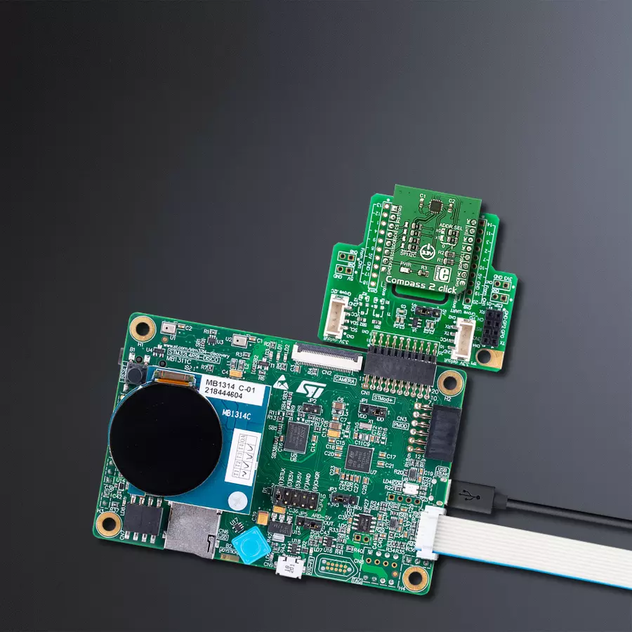
Compass 2 Click
Dev. board
Discovery kit with STM32L4R9AI MCU
Compiler
NECTO Studio
MCU
STM32L4R9AI
Experience the future of direction-finding with our electronic compass technology. It offers precision and responsiveness, making it an essential tool for applications based on position detection, navigation, and orientation.
A
A
Hardware Overview
How does it work?
Compass 2 Click is based on the AK8963, a 3-axis electronic compass from AKM Semiconductor. This electronic compass includes an A/D converter for magnetometer data output in two selectable resolutions. The sensitivity for 14-bit resolution is typically 0.6μT/LSB, while for 16-bit, it is typically 0.15μT/LSB. Some other functions built into this electronic compass are a power-on reset circuit, a data-ready indicator, a magnetic sensor overflow monitor function, a self-test function for a built-in internal magnetic source, and very low power consumption. The AK8963 has several operating modes. All internal circuits are turned off in Power-down mode while all registers are accessible (fuse ROM data cannot be read correctly). In Signal measurement mode, the sensor is measured, and data is processed. The Continuous measurement
mode differs from the Single measurement because the sensor is measured periodically at 8Hz or 100Hz, after which the data is processed. The third measurement mode is an External trigger measurement that will start after the AK8963 gets a trigger input. To check if the sensor is working normally, AK8963 uses the Self-test mode. This test the AK8963 achieves by generating a magnetic field by its internal magnetic source, and then the sensor is measured. The last is the Fuse ROM access mode, which reads Fuse ROM data (sensitivity adjustment data for each axis). This Click board™ allows the use of both I2C and SPI interfaces. Selection is made by positioning SMD jumpers marked SPI I2C to the appropriate position. All jumpers must be on the same side, or the Click
board™ may become unresponsive. When the I2C interface is selected, the AK8963 allows the choice of its I2C address, using the ADDR SEL SMD jumper set to an appropriate position marked 1 or 0. In addition to the general reset function (RST pin), there is also the INT pin used as an interrupt signal to tell the host MCU about the status of the AK8963, and the TRG pin which serves as a trigger pin to make the AK8963 to enter the External Trigger measurement mode. This Click board™ can be operated only with a 3.3V logic voltage level. The board must perform appropriate logic voltage level conversion before using MCUs with different logic levels. Also, it comes equipped with a library containing functions and an example code that can be used as a reference for further development.


Features overview
Development board
Discovery kit with STM32L4R9AI MCU is a complete demonstration and development platform for the STMicroelectronics Arm® Cortex®-M4 core-based STM32L4R9AI microcontroller. Leveraging the innovative ultra-low-power oriented features, 640 Kbytes of embedded RAM, graphics performance (Chrom-ART Accelerator™), and DSISM controller offered by the STM32L4R9AI, the 32L4R9IDISCOVERY kit enables users to easily prototype applications with state-of-the-art energy efficiency, as well as providing stunning audio and graphics rendering with direct support for an AMOLED DSI round display. For even more user friendliness, the on-board ST-LINK/V2-1 debugger provides out-of-the-box programming and
debugging capabilities. The STM32L4R9AI microcontroller features four I2Cs, five USARTs, one ULP UART, three SPIs, two SAIs, one SDIO, one USB 2.0 full-speed OTG, two CANs, one FMC parallel synchronous interface, one 12 bit ADC, one 12-bit DAC, two ULP analog comparators, two op-amps, one two data-lane DSI display, one digital filter for sigma-delta modulation and SWP interface, two Octo-SPI interfaces, an 8- to 14-bit camera interface, one touch-sensing controller interface, JTAG, and SWD debugging support. This Discovery board offers everything users need to get started quickly and develop applications easily. The hardware features on the board help to evaluate the following peripherals: USB OTG FS, microSD™
card, 8-bit camera interface, 16-Mbit PSRAM, PMOD, and STMod+ connectors, IDD measurement, full-duplex I2S with an audio codec and stereo headset jack including an analog microphone, DFSDM with a pair of MEMS digital microphones on board, 512-Mbit Octo-SPI Flash memory device, I2C extension connector, 1.2" AMOLED display using a one data-lane DSI interface with a capacitive touch panel. The ARDUINO® compatible connectors expand the functionality with a wide choice of specialized shields. The integrated ST-LINK/V2-1 provides an embedded in-circuit debugger and programmer for the STM32 MCU.

Microcontroller Overview
MCU Card / MCU
Architecture
ARM Cortex-M4
MCU Memory (KB)
2048
Silicon Vendor
STMicroelectronics
Pin count
169
RAM (Bytes)
655360
Used MCU Pins
mikroBUS™ mapper
Take a closer look
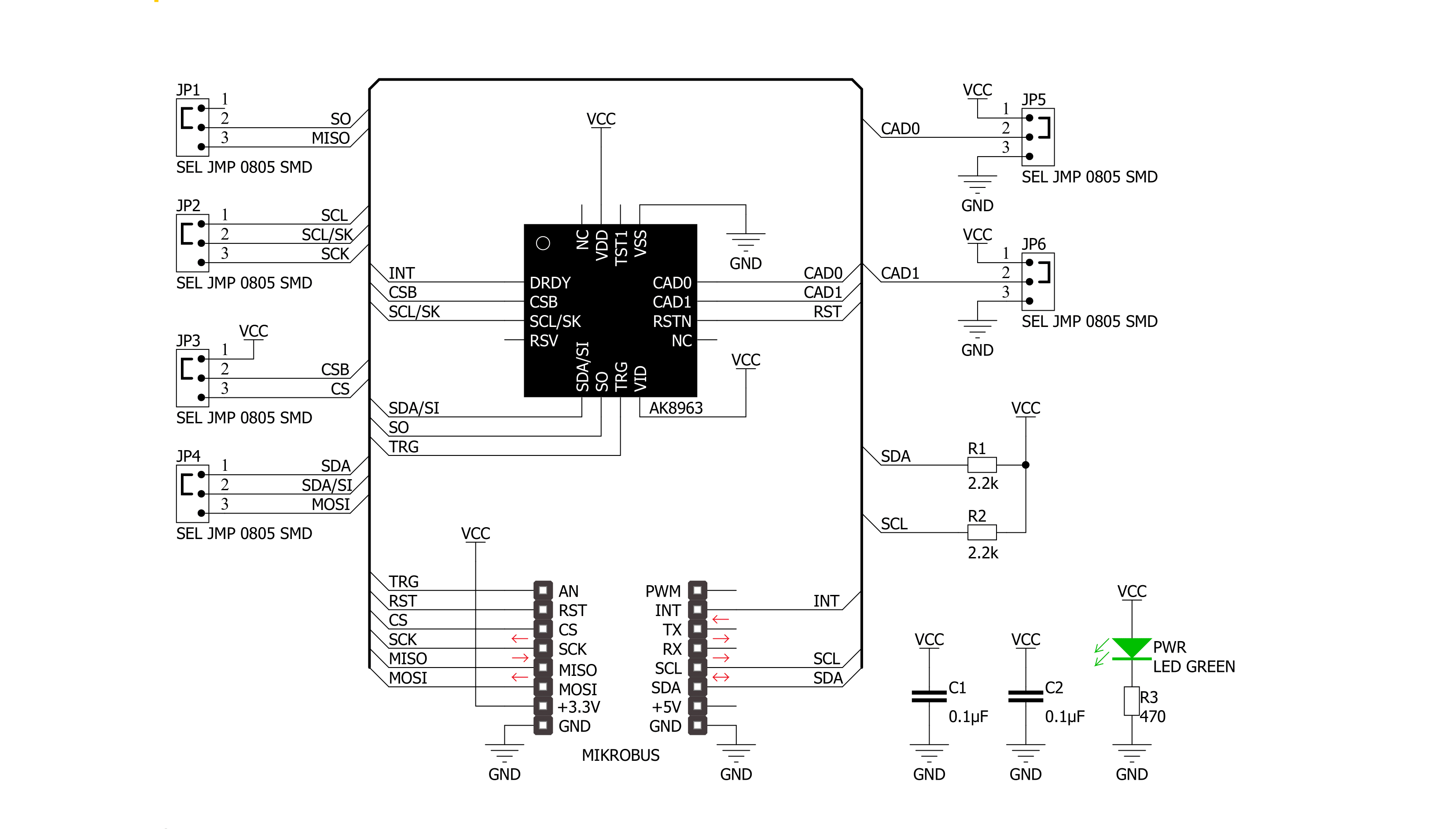
Click board™ Schematic
Step by step
Project assembly

Start by selecting your development board and Click board™. Begin with the Discovery kit with STM32L4R9AI MCU as your development board.


Track your results in real time
Application Output
1. Application Output - In Debug mode, the 'Application Output' window enables real-time data monitoring, offering direct insight into execution results. Ensure proper data display by configuring the environment correctly using the provided tutorial.

2. UART Terminal - Use the UART Terminal to monitor data transmission via a USB to UART converter, allowing direct communication between the Click board™ and your development system. Configure the baud rate and other serial settings according to your project's requirements to ensure proper functionality. For step-by-step setup instructions, refer to the provided tutorial.

3. Plot Output - The Plot feature offers a powerful way to visualize real-time sensor data, enabling trend analysis, debugging, and comparison of multiple data points. To set it up correctly, follow the provided tutorial, which includes a step-by-step example of using the Plot feature to display Click board™ readings. To use the Plot feature in your code, use the function: plot(*insert_graph_name*, variable_name);. This is a general format, and it is up to the user to replace 'insert_graph_name' with the actual graph name and 'variable_name' with the parameter to be displayed.

Software Support
Library Description
This library contains API for Compass 2 Click driver.
Key functions:
compass2_get_axis_data- This function gets the data from one specified axiscompass2_new_measurement- This function prepares the device for a new measurementcompass2_reset- This function does a hardware reset of the device.
Open Source
Code example
The complete application code and a ready-to-use project are available through the NECTO Studio Package Manager for direct installation in the NECTO Studio. The application code can also be found on the MIKROE GitHub account.
/*!
 * \file
 * \brief Comass2 Click example
 *
 * # Description
 * The example prepares the device for a new measurement and reads and displays data from all three axes.
 *
 * The demo application is composed of two sections :
 *
 * ## Application Init
 * Initializes and configures the Click and logger modules.
 *
 * ## Application Task
 * Reads and displays data from all three axes every two seconds.
 *
 * \author MikroE Team
 *
 */
// ------------------------------------------------------------------- INCLUDES

#include "board.h"
#include "log.h"
#include "compass2.h"

// ------------------------------------------------------------------ VARIABLES

static compass2_t compass2;
static log_t logger;

// ------------------------------------------------------ APPLICATION FUNCTIONS

void application_init ( )
{
    log_cfg_t log_cfg;
    compass2_cfg_t cfg;

    /**
     * Logger initialization.
     * Default baud rate: 115200
     * Default log level: LOG_LEVEL_DEBUG
     * @note If USB_UART_RX and USB_UART_TX
     * are defined as HAL_PIN_NC, you will
     * need to define them manually for log to work.
     * See @b LOG_MAP_USB_UART macro definition for detailed explanation.
     */
    LOG_MAP_USB_UART( log_cfg );
    log_init( &logger, &log_cfg );
    log_info( &logger, "---- Application Init ----" );

    //  Click initialization.

    compass2_cfg_setup( &cfg );
    COMPASS2_MAP_MIKROBUS( cfg, MIKROBUS_1 );
    compass2_init( &compass2, &cfg );

    compass2_reset( &compass2 );
    Delay_ms ( 100 );

    compass2_default_cfg( &compass2 );
    Delay_ms ( 100 );
}

void application_task ( )
{
    int16_t x_axis;
    int16_t y_axis;
    int16_t z_axis;

    compass2_new_measurement( &compass2 );

    log_printf( &logger, " --- Axis ---\r\n" );

    x_axis = compass2_get_axis_data( &compass2, COMPASS2_X_AXIS );
    y_axis = compass2_get_axis_data( &compass2, COMPASS2_Y_AXIS );
    z_axis = compass2_get_axis_data( &compass2, COMPASS2_Z_AXIS );

    log_printf( &logger, "X: %d\r\n", x_axis );
    log_printf( &logger, "Y: %d\r\n", y_axis );
    log_printf( &logger, "Z: %d\r\n", z_axis );

    log_printf( &logger, "----------------\r\n" );

    Delay_ms ( 1000 );
    Delay_ms ( 1000 );
}

int main ( void )
{
    /* Do not remove this line or clock might not be set correctly. */
    #ifdef PREINIT_SUPPORTED
    preinit();
    #endif

    application_init( );

    for ( ; ; )
    {
        application_task( );
    }

    return 0;
}

// ------------------------------------------------------------------------ END


