Decode the absolute angular position of a permanent magnet using AAS33001 and PIC32MZ2048EFM100
360 degrees of certainty: Absolute angular positioning, no compromises!

Published Nov 12, 2023
Click board™
Angle 9 Click
Dev. board
Curiosity PIC32 MZ EF
Compiler
NECTO Studio
MCU
PIC32MZ2048EFM100
Our solution, dedicated to detecting the absolute angular position of a permanent magnet, opens the door to a new era of precision, ensuring unparalleled accuracy in rotational measurements for your applications.
A
A
Hardware Overview
How does it work?
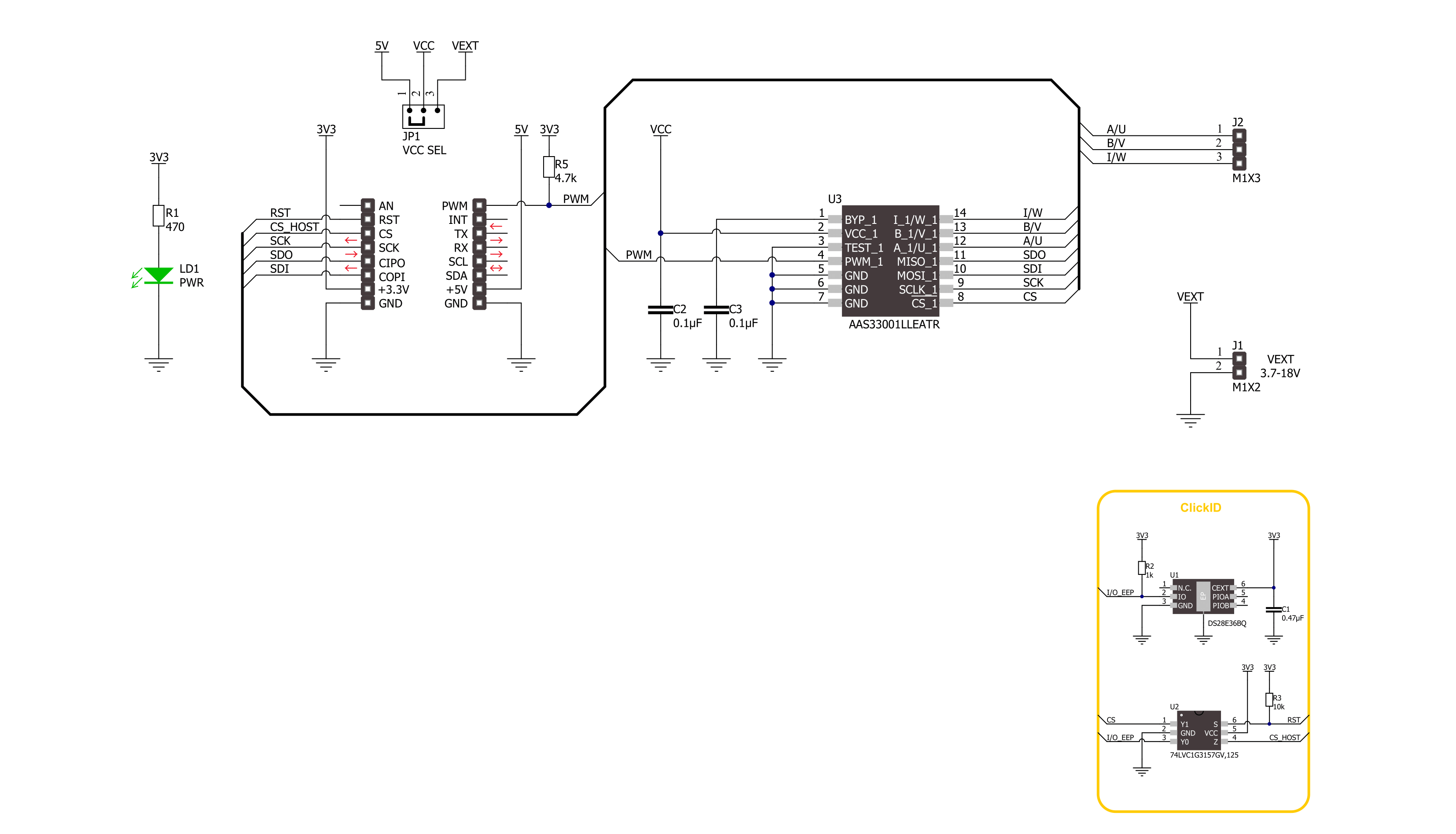
Angle 9 Click is based on the AAS33001, a precision angle sensor with incremental and motor commutation outputs and on-chip linearization from Allegro Microsystems. It is a rotary position circular vertical Hall-sensor-based device (CVH), incorporating one electrically independent Hall sensor die, thus providing solid-state consistency and reliability. The Hall sensor measures the magnetic field vector through a 360° in the x-y plane parallel to the face of the angle sensor. The Hall sensor also computes an angle measurement based on the actual physical reading and internal parameters that the user has set. The Angle 9 Click can monitor the angular position of a rotating magnet at speeds ranging from 0 up to 15,000 RPM with a refresh rate of 1μs. It is a unique addition that can be used alongside a precision angle sensor, allowing fast prototyping and quick
measurement during development. This magnetic holder is an adjustable shaft with a 6mm diameter magnet that can be positioned right above the angle sensor. The Ange 9 Click also has a header that allows you to use it with additional devices over the ABI and UVW interfaces. Both interfaces use all three pins (A/U, B/V, I/W), so you can’t use both at the same time. The Incremental Output Interface (ABI) is available in the form of quadrature A/B and Index outputs to emulate an optical or mechanical encoder. The brushless DC motor output is available over the U, V, and W signals for stator commutation of brushless DC (BLDC). The device is mode-selectable for 1 to 16 pole pairs. PWM output is always resolved to a 12-bit angle resolution. The external power supply can be selected over the VCC SEL jumper with 5V from the mikroBUS™ socket chosen by default.
The external power supply can range from 3.7 to 18V and be connected over the header terminal. Angle 9 Click uses a full-duplex standard 4-Wire SPI serial interface to communicate with the host MCU, using SPI mode 3 and supporting frequencies up to 10MHz. The readout is possible with a 12-bit resolution with error flags or a 15-bit resolution without error flags. The angle sensor can be reset over the RST pin. The PWM interface over the PWM pin provides the initial position for ABI/UVW interfaces. This Click board™ can only be operated with a 3.3V logic voltage level. The board must perform appropriate logic voltage level conversion before using MCUs with different logic levels. Also, it comes equipped with a library containing functions and an example code that can be used as a reference for further development.

Features overview
Development board
Curiosity PIC32 MZ EF development board is a fully integrated 32-bit development platform featuring the high-performance PIC32MZ EF Series (PIC32MZ2048EFM) that has a 2MB Flash, 512KB RAM, integrated FPU, Crypto accelerator, and excellent connectivity options. It includes an integrated programmer and debugger, requiring no additional hardware. Users can expand
functionality through MIKROE mikroBUS™ Click™ adapter boards, add Ethernet connectivity with the Microchip PHY daughter board, add WiFi connectivity capability using the Microchip expansions boards, and add audio input and output capability with Microchip audio daughter boards. These boards are fully integrated into PIC32’s powerful software framework, MPLAB Harmony,
which provides a flexible and modular interface to application development a rich set of inter-operable software stacks (TCP-IP, USB), and easy-to-use features. The Curiosity PIC32 MZ EF development board offers expansion capabilities making it an excellent choice for a rapid prototyping board in Connectivity, IOT, and general-purpose applications.

Microcontroller Overview
MCU Card / MCU

Architecture
PIC32
MCU Memory (KB)
2048
Silicon Vendor
Microchip
Pin count
100
RAM (Bytes)
524288
You complete me!
Accessories
Rotary Magnetic Holder is an addition designed for use alongside a magnetic rotary position sensor. It comes with a plastic stand measuring 22x16x10 millimeters (L x W x H), as well as an adjustable shaft with a 6mm diameter magnet. The plastic frame has four round feet that fit into holes in the board near the magnetic rotary position sensor, with a 6mm diameter hole on top to match the adjustable shaft that carries the magnet. This shaft has a height adjustment screw on it, allowing the user to adjust it between 18 and 22 millimeters. This way, fast prototyping and quick measurements of the magnet characteristics are allowed during development.

Used MCU Pins
mikroBUS™ mapper
Take a closer look
Click board™ Schematic
Step by step
Project assembly

Start by selecting your development board and Click board™. Begin with the Curiosity PIC32 MZ EF as your development board.


Track your results in real time
Application Output
1. Application Output - In Debug mode, the 'Application Output' window enables real-time data monitoring, offering direct insight into execution results. Ensure proper data display by configuring the environment correctly using the provided tutorial.

2. UART Terminal - Use the UART Terminal to monitor data transmission via a USB to UART converter, allowing direct communication between the Click board™ and your development system. Configure the baud rate and other serial settings according to your project's requirements to ensure proper functionality. For step-by-step setup instructions, refer to the provided tutorial.

3. Plot Output - The Plot feature offers a powerful way to visualize real-time sensor data, enabling trend analysis, debugging, and comparison of multiple data points. To set it up correctly, follow the provided tutorial, which includes a step-by-step example of using the Plot feature to display Click board™ readings. To use the Plot feature in your code, use the function: plot(*insert_graph_name*, variable_name);. This is a general format, and it is up to the user to replace 'insert_graph_name' with the actual graph name and 'variable_name' with the parameter to be displayed.

Software Support
Library Description
This library contains API for Angle 9 Click driver.
Key functions:
angle9_read_angle- This function reads the magnetic angular position in degrees.angle9_read_field_strength- This function reads the magnetic field strength in gauss.angle9_read_temperature- This function reads the sensor internal temperature in degrees celsius.
Open Source
Code example
The complete application code and a ready-to-use project are available through the NECTO Studio Package Manager for direct installation in the NECTO Studio. The application code can also be found on the MIKROE GitHub account.
/*!
 * @file main.c
 * @brief Angle 9 Click example
 *
 * # Description
 * This example demonstrates the use of Angle 9 Click board by reading and displaying
 * the magnet's angular position in degrees, field strength in gauss, and the internal
 * sensor temperature in degrees celsius.
 *
 * The demo application is composed of two sections :
 *
 * ## Application Init
 * Initializes the driver and logger.
 *
 * ## Application Task
 * Reads the magnet's angular position in degrees, magnetic field strength in gauss,
 * and the internal sensor temperature in degrees celsius and displays the results
 * on the USB UART approximately every 100ms.
 *
 * @author Stefan Filipovic
 *
 */

#include "board.h"
#include "log.h"
#include "angle9.h"

static angle9_t angle9;
static log_t logger;

void application_init ( void )
{
    log_cfg_t log_cfg;  /**< Logger config object. */
    angle9_cfg_t angle9_cfg;  /**< Click config object. */

    /**
     * Logger initialization.
     * Default baud rate: 115200
     * Default log level: LOG_LEVEL_DEBUG
     * @note If USB_UART_RX and USB_UART_TX
     * are defined as HAL_PIN_NC, you will
     * need to define them manually for log to work.
     * See @b LOG_MAP_USB_UART macro definition for detailed explanation.
     */
    LOG_MAP_USB_UART( log_cfg );
    log_init( &logger, &log_cfg );
    log_info( &logger, " Application Init " );

    // Click initialization.
    angle9_cfg_setup( &angle9_cfg );
    ANGLE9_MAP_MIKROBUS( angle9_cfg, MIKROBUS_1 );
    if ( SPI_MASTER_ERROR == angle9_init( &angle9, &angle9_cfg ) )
    {
        log_error( &logger, " Communication init." );
        for ( ; ; );
    }

    log_info( &logger, " Application Task " );
}

void application_task ( void )
{
    float angle = 0;
    float int_temp = 0;
    uint16_t field_str = 0;
    if ( ANGLE9_OK == angle9_read_angle ( &angle9, &angle ) )
    {
        log_printf ( &logger, " Angle: %.1f deg\r\n", angle );
        if ( ANGLE9_OK == angle9_read_field_strength ( &angle9, &field_str ) )
        {
            log_printf ( &logger, " Field strength: %u Gauss\r\n", field_str );
        }
        if ( ANGLE9_OK == angle9_read_temperature ( &angle9, &int_temp ) )
        {
            log_printf ( &logger, " Internal temperature: %.2f degC\r\n\n", int_temp );
        }
        Delay_ms ( 100 );
    }
}

int main ( void )
{
    /* Do not remove this line or clock might not be set correctly. */
    #ifdef PREINIT_SUPPORTED
    preinit();
    #endif

    application_init( );

    for ( ; ; )
    {
        application_task( );
    }

    return 0;
}

// ------------------------------------------------------------------------ END


