Monitor and respond to variations in light intensity using BH1620FVC and PIC32MZ2048EFM100
Capturing lightscapes: The artistry of ambient sensor tech

Published Sep 24, 2023
Click board™
Ambient 12 Click
Dev. board
Curiosity PIC32 MZ EF
Compiler
NECTO Studio
MCU
PIC32MZ2048EFM100
Unveil the potential of our ambient light intensity sensing in autonomous systems, where it plays a crucial role in object recognition and environmental perception
A
A
Hardware Overview
How does it work?
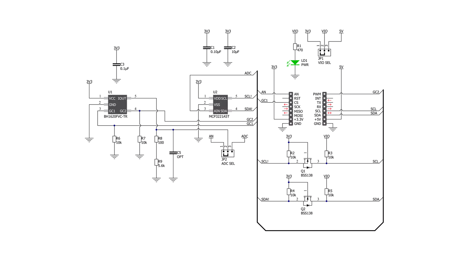
Ambient 12 Click is based on the BH1620FVC, an analog current-output ambient light sensor from Rohm Semiconductor. The BH1620FVC comprises photodiodes, amplifiers, and current mirror circuits, where the output current, in proportion to brightness, is converted to the voltage value by an external resistor. It is characterized by spectral sensitivity close to human eyes sensitivity with low sensitivity variations of +/-15%. It also has four configurable modes of operation: shutdown mode associated with three gain modes: high-gain
mode with an illuminance detection range of 1000lx, medium-gain mode up to 10.000lx, and low-gain mode up to 100.000lx. The desired gain mode is selected through CS and PWM pins of the mikroBUS™ socket labeled GC1 and GC2. The output voltage of the BH1620FVC can be converted to a digital value using MCP3221, a successive approximation A/D converter with a 12-bit resolution from Microchip, using a 2-wire I2C compatible interface, or can be sent directly to an analog pin of the mikroBUS™ socket labeled as
AN. Selection can be performed by onboard SMD jumper labeled as A/D SEL to an appropriate position marked as AN and ADC. This Click board™ can operate with either 3.3V or 5V logic voltage levels selected via the VIO SEL jumper. This way, both 3.3V and 5V capable MCUs can use the communication lines properly. Also, this Click board™ comes equipped with a library containing easy-to-use functions and an example code that can be used as a reference for further development.


Features overview
Development board
Curiosity PIC32 MZ EF development board is a fully integrated 32-bit development platform featuring the high-performance PIC32MZ EF Series (PIC32MZ2048EFM) that has a 2MB Flash, 512KB RAM, integrated FPU, Crypto accelerator, and excellent connectivity options. It includes an integrated programmer and debugger, requiring no additional hardware. Users can expand
functionality through MIKROE mikroBUS™ Click™ adapter boards, add Ethernet connectivity with the Microchip PHY daughter board, add WiFi connectivity capability using the Microchip expansions boards, and add audio input and output capability with Microchip audio daughter boards. These boards are fully integrated into PIC32’s powerful software framework, MPLAB Harmony,
which provides a flexible and modular interface to application development a rich set of inter-operable software stacks (TCP-IP, USB), and easy-to-use features. The Curiosity PIC32 MZ EF development board offers expansion capabilities making it an excellent choice for a rapid prototyping board in Connectivity, IOT, and general-purpose applications.

Microcontroller Overview
MCU Card / MCU

Architecture
PIC32
MCU Memory (KB)
2048
Silicon Vendor
Microchip
Pin count
100
RAM (Bytes)
524288
Used MCU Pins
mikroBUS™ mapper
Take a closer look
Click board™ Schematic
Step by step
Project assembly

Start by selecting your development board and Click board™. Begin with the Curiosity PIC32 MZ EF as your development board.


Track your results in real time
Application Output
1. Application Output - In Debug mode, the 'Application Output' window enables real-time data monitoring, offering direct insight into execution results. Ensure proper data display by configuring the environment correctly using the provided tutorial.

2. UART Terminal - Use the UART Terminal to monitor data transmission via a USB to UART converter, allowing direct communication between the Click board™ and your development system. Configure the baud rate and other serial settings according to your project's requirements to ensure proper functionality. For step-by-step setup instructions, refer to the provided tutorial.

3. Plot Output - The Plot feature offers a powerful way to visualize real-time sensor data, enabling trend analysis, debugging, and comparison of multiple data points. To set it up correctly, follow the provided tutorial, which includes a step-by-step example of using the Plot feature to display Click board™ readings. To use the Plot feature in your code, use the function: plot(*insert_graph_name*, variable_name);. This is a general format, and it is up to the user to replace 'insert_graph_name' with the actual graph name and 'variable_name' with the parameter to be displayed.

Software Support
Library Description
This library contains API for Ambient 12 Click driver.
Key functions:
ambient12_read_adc_voltage- This function reads raw 12-bit ADC data and converts it to voltage by using I2C serial interfaceambient12_voltage_to_lux- This function calculates illuminance (lux) based on the voltage inputambient12_set_gain_mode- This function sets the gain mode.
Open Source
Code example
The complete application code and a ready-to-use project are available through the NECTO Studio Package Manager for direct installation in the NECTO Studio. The application code can also be found on the MIKROE GitHub account.
/*!
 * @file main.c
 * @brief Ambient 12 Click Example.
 *
 * # Description
 * This example demonstrates the use of Ambient 12 Click board.
 *
 * The demo application is composed of two sections :
 *
 * ## Application Init
 * Initializes the driver and sets the gain mode to M-Gain which can detect the illuminance of up to 10000 lux.
 *
 * ## Application Task
 * Reads the ADC voltage and then calculates the illuminance from it.
 * The calculated value of illuminance in lux is being displayed on the USB UART approximately once per second.
 *
 * @author Stefan Filipovic
 *
 */

#include "board.h"
#include "log.h"
#include "ambient12.h"

static ambient12_t ambient12;       /**< Ambient 12 Click driver object. */
static log_t logger;                /**< Logger object. */

void application_init ( void )
{
    log_cfg_t log_cfg;              /**< Logger config object. */
    ambient12_cfg_t ambient12_cfg;  /**< Click config object. */

    /**
     * Logger initialization.
     * Default baud rate: 115200
     * Default log level: LOG_LEVEL_DEBUG
     * @note If USB_UART_RX and USB_UART_TX
     * are defined as HAL_PIN_NC, you will
     * need to define them manually for log to work.
     * See @b LOG_MAP_USB_UART macro definition for detailed explanation.
     */
    LOG_MAP_USB_UART( log_cfg );
    log_init( &logger, &log_cfg );
    Delay_ms ( 100 );
    log_info( &logger, " Application Init " );

    // Click initialization.
    ambient12_cfg_setup( &ambient12_cfg );
    AMBIENT12_MAP_MIKROBUS( ambient12_cfg, MIKROBUS_1 );
    if ( ADC_ERROR == ambient12_init( &ambient12, &ambient12_cfg ) )
    {
        log_error( &logger, " Application Init Error. " );
        log_info( &logger, " Please, run program again... " );

        for ( ; ; );
    }

    ambient12_set_gain_mode ( &ambient12, AMBIENT12_MODE_M_GAIN );
    log_printf( &logger, " M-Gain mode selected.\r\n Up to 10000 lux can be measured.\r\n" );
    log_info( &logger, " Application Task " );
}

void application_task ( void )
{
    float voltage = 0;

    if ( AMBIENT12_OK == ambient12_read_adc_voltage ( &ambient12, &voltage ) )
    {
        log_printf( &logger, " Illuminance : %ld Lux\r\n\n", ambient12_voltage_to_lux( &ambient12, voltage ) );
    }

    Delay_ms ( 1000 );
}

int main ( void )
{
    /* Do not remove this line or clock might not be set correctly. */
    #ifdef PREINIT_SUPPORTED
    preinit();
    #endif

    application_init( );

    for ( ; ; )
    {
        application_task( );
    }

    return 0;
}

// ------------------------------------------------------------------------ END


