Measure distances quickly and precisely using RFD77402 and PIC32MZ2048EFM100
Solution based on ToF (Time of Flight) measurement principle
Published Sep 21, 2023
Click board™
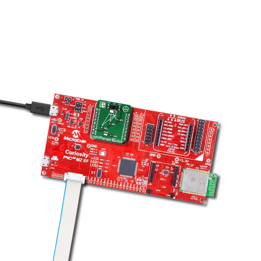
LightRanger 3 Click
Dev. board
Curiosity PIC32 MZ EF
Compiler
NECTO Studio
MCU
PIC32MZ2048EFM100
Unlock new dimensions in distance measurement with our ToF solution, designed to enhance object detection, navigation, and spatial mapping in an array of fields
A
A
Hardware Overview
How does it work?
LightRanger 3 Click is based on the RFD77402, a ToF sensor module from RF Digital. This sensor uses the VCSE (Vertical Cavity Surface Emitting) narrowband LASER, which emits light in the range of 850 nm. The light emission is in the IR range of the spectrum and it is not visible by a human eye. It is received by the IR sensor and processed by the integrated sections of the RFD77402, giving an 11-bit result on the output register, available via the standard I2C interface. The device is rated as Class 1 LASER product, and it does not cause harmful eye injuries. However, it should not be pointed towards the eyes. The highly integrated RFD77402 ToF sensor encompasses several integrated sections. It has an embedded MCU, OTP memory, RAM area, ranging processing unit and the VCSEL driver. It exposes a simple I2C interface for the communication with the host MCU, offering a range of registers, used for configuring and status reporting. In addition, it offers an interrupt pin (INT) routed to the INT pin of the mikroBUS™.
Highly configurable interrupt engine allows this pin to be configured to generate interrupt signals for various events, alerting the host MCU about some important status changes, such as the Data Ready event, for example. It can be set to work in both open-drain configurations, as well as in the push-pull mode. The Click board™ is equipped with the 10K pull-up resistor, so it is advised to configure the INT pin in open-drain mode. The measurement is done by comparing the modulation shift of the light in the reflected beam. Therefore, the range and the accuracy depend on the material of the measured object, as well as the photo - pollution of the IR spectrum. The module is designed to suppress the noise and interference. The narrow Field of Illumination (29°) allows focused measurement and prevents beam scattering. The receiver has a bit wider Field of View (55°), allowing it to catch the reflected beam. The measurement is naturally affected by the IR reflectance of an object, so best results are
achieved when measuring the distance of the objects that have high IR reflectance. The maximum range that can be measured is 2000mm, while the minimum operational range is 100mm. The measurement error is linear, and it grows with the distance. It stays within 10% of the distance The Click board™ uses only 3.3V power rail from the mikroBUS™. No additional jumpers or selectors exist on the Click board™ since the RFD77402 ToF sensor module is highly integrated and requires a minimum number of external components to work. The RFD77402 module datasheet offers an extensive information about internal registers and how to configure them. However, the click comes with the library of functions that provide simplified operation and measurement. The use of these functions is demonstrated in the example, which can be used as the reference for custom design.


Features overview
Development board
Curiosity PIC32 MZ EF development board is a fully integrated 32-bit development platform featuring the high-performance PIC32MZ EF Series (PIC32MZ2048EFM) that has a 2MB Flash, 512KB RAM, integrated FPU, Crypto accelerator, and excellent connectivity options. It includes an integrated programmer and debugger, requiring no additional hardware. Users can expand
functionality through MIKROE mikroBUS™ Click™ adapter boards, add Ethernet connectivity with the Microchip PHY daughter board, add WiFi connectivity capability using the Microchip expansions boards, and add audio input and output capability with Microchip audio daughter boards. These boards are fully integrated into PIC32’s powerful software framework, MPLAB Harmony,
which provides a flexible and modular interface to application development a rich set of inter-operable software stacks (TCP-IP, USB), and easy-to-use features. The Curiosity PIC32 MZ EF development board offers expansion capabilities making it an excellent choice for a rapid prototyping board in Connectivity, IOT, and general-purpose applications.

Microcontroller Overview
MCU Card / MCU

Architecture
PIC32
MCU Memory (KB)
2048
Silicon Vendor
Microchip
Pin count
100
RAM (Bytes)
524288
Used MCU Pins
mikroBUS™ mapper
Take a closer look
Click board™ Schematic

Step by step
Project assembly

Start by selecting your development board and Click board™. Begin with the Curiosity PIC32 MZ EF as your development board.


Software Support
Library Description
This library contains API for LightRanger 3 Click driver.
Key functions:
lightranger3_set_measurement_mode- This function go to measurement modelightranger3_get_distance- This function reads distancelightranger3_get_confidence_value- This function reads confidence value.
Open Source
Code example
The complete application code and a ready-to-use project are available through the NECTO Studio Package Manager for direct installation in the NECTO Studio. The application code can also be found on the MIKROE GitHub account.
/*!
 * \file
 * \brief LightRanger3 Click example
 *
 * # Description
 * This app precisely measure distance without making actual contact.
 *
 * The demo application is composed of two sections :
 *
 * ## Application Init
 * Initializes driver init and configuration chip.
 *
 * ## Application Task
 * Includes measurements, reads distance, and logs distance to USBUART for every 300 ms.
 * Distance measurement at distances ranging from 100 mm to 2000 mm.
 *
 * \author MikroE Team
 *
 */
// ------------------------------------------------------------------- INCLUDES

#include "board.h"
#include "log.h"
#include "lightranger3.h"

// ------------------------------------------------------------------ VARIABLES

static lightranger3_t lightranger3;
static log_t logger;

// ------------------------------------------------------ APPLICATION FUNCTIONS

void application_init ( void )
{
    log_cfg_t log_cfg;
    lightranger3_cfg_t cfg;
    uint8_t init_status;

    /**
     * Logger initialization.
     * Default baud rate: 115200
     * Default log level: LOG_LEVEL_DEBUG
     * @note If USB_UART_RX and USB_UART_TX
     * are defined as HAL_PIN_NC, you will
     * need to define them manually for log to work.
     * See @b LOG_MAP_USB_UART macro definition for detailed explanation.
     */
    LOG_MAP_USB_UART( log_cfg );
    log_init( &logger, &log_cfg );
    log_info( &logger, "---- Application Init ----" );

    //  Click initialization.

    lightranger3_cfg_setup( &cfg );
    LIGHTRANGER3_MAP_MIKROBUS( cfg, MIKROBUS_1 );
    lightranger3_init( &lightranger3, &cfg );

    init_status = lightranger3_device_init( &lightranger3 );

    if ( init_status == 0 )
    {
        log_printf( &logger, " --- Device init successfully --- \r\n " );
    }
    else
    {
        log_printf( &logger, " ---  Device init error --- \r\n " );
    }
}

void application_task ( void )
{
    uint16_t distance;

    lightranger3_take_single_measurement( &lightranger3 );

    distance = lightranger3_get_distance( &lightranger3 );

    log_printf( &logger, "Distance = %u mm \r\n ", distance );

    Delay_ms ( 300 );
}

int main ( void )
{
    /* Do not remove this line or clock might not be set correctly. */
    #ifdef PREINIT_SUPPORTED
    preinit();
    #endif

    application_init( );

    for ( ; ; )
    {
        application_task( );
    }

    return 0;
}

// ------------------------------------------------------------------------ END
Additional Support
Resources
Category:Optical


