Upgrade your temperature sensing experience with STTS22H and STM32F410RB
Reliable readings, every time

Published Oct 08, 2024
Click board™
Thermo 14 Click
Dev. board
Nucleo 64 with STM32F410RB MCU
Compiler
NECTO Studio
MCU
STM32F410RB
Count on our temperature measurement solution for consistently reliable temperature readings in any situation.
A
A
Hardware Overview
How does it work?
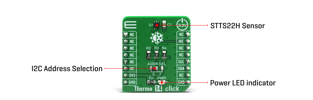
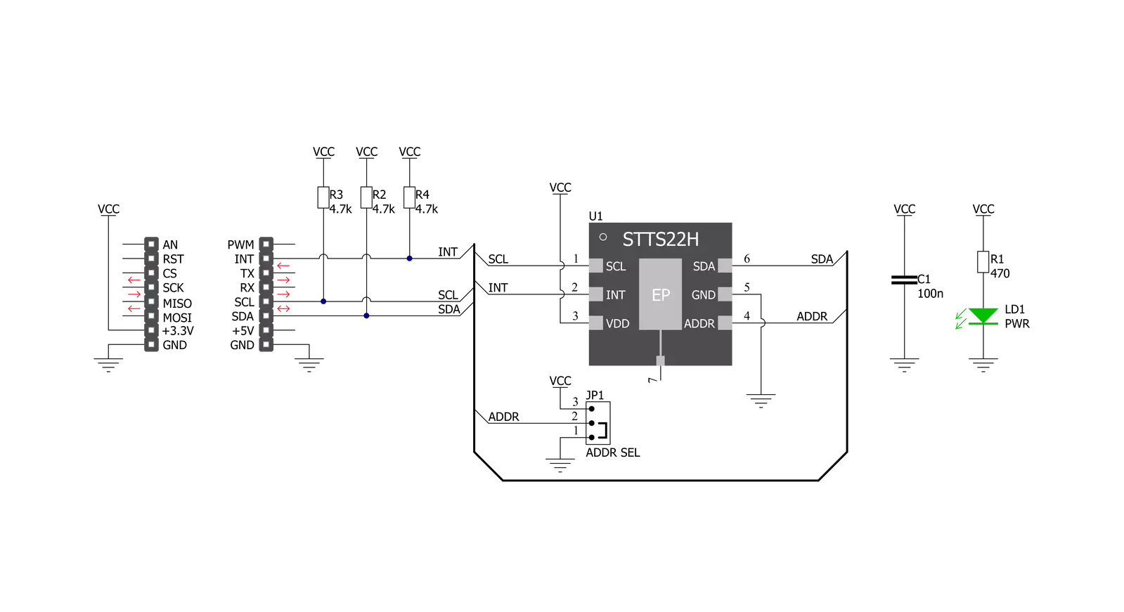
Thermo 14 Click is based on the STTS22H, a high accuracy temperature sensor IC with the 2-Wire interface, from STMicroelectronics. The sensor operating mode is user-configurable and allows selecting between different ODRs (down to 1 Hz) or the one-shot mode for battery saving. In one-shot mode, the sensor current consumption falls to 1.75 µA. The Click board™ itself has a reasonably small number of components because most of the measurement circuitry is already integrated on the STTS22H sensor. The I2C / SMBus 3.0
compatible serial interface lines, along with the INT pin, which also works in the open drain configuration, are pulled up by the onboard resistors. The 2-Wire lines are routed to the respective I2C lines of the mikroBUS™ (SCK and SDA), while the INT pin is routed to the INT pin of the mikroBUS™. The STTS22H INT pin is asserted (low) whenever the temperature is equal to or exceeds the high limit or is below the low limit. Once asserted, the output will remain asserted until the STTS22H receives an SMBus Alert
Response Address (ARA) from the host and acknowledges with its slave address. The I2C address can be selected with the ADDR SEL onboard SMD jumper. The I2C address can be changed by this jumper, allowing for more than one of these click boards to be used on a system, each with the different I2C address. This Click Board™ is designed to be operated only with 3.3V logic level. A proper logic voltage level conversion should be performed before the Click board™ is used with MCUs with logic levels of 5V.
Features overview
Development board
Nucleo-64 with STM32F410RB MCU offers a cost-effective and adaptable platform for developers to explore new ideas and prototype their designs. This board harnesses the versatility of the STM32 microcontroller, enabling users to select the optimal balance of performance and power consumption for their projects. It accommodates the STM32 microcontroller in the LQFP64 package and includes essential components such as a user LED, which doubles as an ARDUINO® signal, alongside user and reset push-buttons, and a 32.768kHz crystal oscillator for precise timing operations. Designed with expansion and flexibility in mind, the Nucleo-64 board features an ARDUINO® Uno V3 expansion connector and ST morpho extension pin
headers, granting complete access to the STM32's I/Os for comprehensive project integration. Power supply options are adaptable, supporting ST-LINK USB VBUS or external power sources, ensuring adaptability in various development environments. The board also has an on-board ST-LINK debugger/programmer with USB re-enumeration capability, simplifying the programming and debugging process. Moreover, the board is designed to simplify advanced development with its external SMPS for efficient Vcore logic supply, support for USB Device full speed or USB SNK/UFP full speed, and built-in cryptographic features, enhancing both the power efficiency and security of projects. Additional connectivity is
provided through dedicated connectors for external SMPS experimentation, a USB connector for the ST-LINK, and a MIPI® debug connector, expanding the possibilities for hardware interfacing and experimentation. Developers will find extensive support through comprehensive free software libraries and examples, courtesy of the STM32Cube MCU Package. This, combined with compatibility with a wide array of Integrated Development Environments (IDEs), including IAR Embedded Workbench®, MDK-ARM, and STM32CubeIDE, ensures a smooth and efficient development experience, allowing users to fully leverage the capabilities of the Nucleo-64 board in their projects.

Microcontroller Overview
MCU Card / MCU

Architecture
ARM Cortex-M4
MCU Memory (KB)
128
Silicon Vendor
STMicroelectronics
Pin count
64
RAM (Bytes)
32768
You complete me!
Accessories
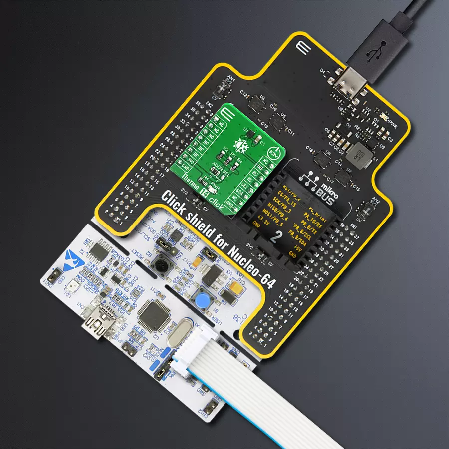
Click Shield for Nucleo-64 comes equipped with two proprietary mikroBUS™ sockets, allowing all the Click board™ devices to be interfaced with the STM32 Nucleo-64 board with no effort. This way, Mikroe allows its users to add any functionality from our ever-growing range of Click boards™, such as WiFi, GSM, GPS, Bluetooth, ZigBee, environmental sensors, LEDs, speech recognition, motor control, movement sensors, and many more. More than 1537 Click boards™, which can be stacked and integrated, are at your disposal. The STM32 Nucleo-64 boards are based on the microcontrollers in 64-pin packages, a 32-bit MCU with an ARM Cortex M4 processor operating at 84MHz, 512Kb Flash, and 96KB SRAM, divided into two regions where the top section represents the ST-Link/V2 debugger and programmer while the bottom section of the board is an actual development board. These boards are controlled and powered conveniently through a USB connection to program and efficiently debug the Nucleo-64 board out of the box, with an additional USB cable connected to the USB mini port on the board. Most of the STM32 microcontroller pins are brought to the IO pins on the left and right edge of the board, which are then connected to two existing mikroBUS™ sockets. This Click Shield also has several switches that perform functions such as selecting the logic levels of analog signals on mikroBUS™ sockets and selecting logic voltage levels of the mikroBUS™ sockets themselves. Besides, the user is offered the possibility of using any Click board™ with the help of existing bidirectional level-shifting voltage translators, regardless of whether the Click board™ operates at a 3.3V or 5V logic voltage level. Once you connect the STM32 Nucleo-64 board with our Click Shield for Nucleo-64, you can access hundreds of Click boards™, working with 3.3V or 5V logic voltage levels.

Used MCU Pins
mikroBUS™ mapper
Take a closer look
Click board™ Schematic
Step by step
Project assembly
Start by selecting your development board and Click board™. Begin with the Nucleo 64 with STM32F410RB MCU as your development board.


Track your results in real time
Application Output
1. Application Output - In Debug mode, the 'Application Output' window enables real-time data monitoring, offering direct insight into execution results. Ensure proper data display by configuring the environment correctly using the provided tutorial.

2. UART Terminal - Use the UART Terminal to monitor data transmission via a USB to UART converter, allowing direct communication between the Click board™ and your development system. Configure the baud rate and other serial settings according to your project's requirements to ensure proper functionality. For step-by-step setup instructions, refer to the provided tutorial.

3. Plot Output - The Plot feature offers a powerful way to visualize real-time sensor data, enabling trend analysis, debugging, and comparison of multiple data points. To set it up correctly, follow the provided tutorial, which includes a step-by-step example of using the Plot feature to display Click board™ readings. To use the Plot feature in your code, use the function: plot(*insert_graph_name*, variable_name);. This is a general format, and it is up to the user to replace 'insert_graph_name' with the actual graph name and 'variable_name' with the parameter to be displayed.

Software Support
Library Description
This library contains API for NAME Click driver.
Key functions:
thermo14_reset- Reset function.thermo14_sensor_enable- Sensor enable function.thermo14_temp_raw_get- Get Raw Temperature Data function.
Open Source
Code example
The complete application code and a ready-to-use project are available through the NECTO Studio Package Manager for direct installation in the NECTO Studio. The application code can also be found on the MIKROE GitHub account.
/*!
 * \file
 * \brief Thermo14 Click example
 *
 * # Description
 * Thermo 14 Click provides an accuracy of ±0.5°C in the range from -10°C to 60°C.
 *
 * The demo application is composed of two sections :
 *
 * ## Application Init
 * Initalizes I2C driver, sets up the device.
 *
 * ## Application Task
 * This example shows capabilities of Thermo 14 Click by measuring
   temperature every 3 seconds and displaying temperature in degrres Celsius via USART terminal.
 *
 *
 * \author MikroE Team
 *
 */
// ------------------------------------------------------------------- INCLUDES

#include "board.h"
#include "log.h"
#include "thermo14.h"

// ------------------------------------------------------------------ VARIABLES

static thermo14_t thermo14;
static log_t logger;

static float temp_val;
static char deg_cel[ 3 ] = { 176, 67, 0 };
static uint16_t disp_temp;

// ------------------------------------------------------- ADDITIONAL FUNCTIONS

void log_display( float value )
{
    disp_temp = ( uint16_t ) value;

    disp_temp = ( uint16_t ) ( value * 100.0 );
}

// ------------------------------------------------------ APPLICATION FUNCTIONS

void application_init ( void )
{
    log_cfg_t log_cfg;
    thermo14_cfg_t cfg;

    /**
     * Logger initialization.
     * Default baud rate: 115200
     * Default log level: LOG_LEVEL_DEBUG
     * @note If USB_UART_RX and USB_UART_TX
     * are defined as HAL_PIN_NC, you will
     * need to define them manually for log to work.
     * See @b LOG_MAP_USB_UART macro definition for detailed explanation.
     */
    LOG_MAP_USB_UART( log_cfg );
    log_init( &logger, &log_cfg );
    log_info( &logger, "---- Application Init ----" );

    //  Click initialization.

    thermo14_cfg_setup( &cfg );
    THERMO14_MAP_MIKROBUS( cfg, MIKROBUS_1 );
    thermo14_init( &thermo14, &cfg );

    Delay_ms ( 100 );
    thermo14_default_cfg( &thermo14 );
}

void application_task ( void )
{
    temp_val = thermo14_get_temperature( &thermo14 );

    log_printf( &logger, " Temperature: %.2f C \r\n ", temp_val );
    Delay_ms ( 1000 );
    Delay_ms ( 1000 );
    Delay_ms ( 1000 );
}

int main ( void )
{
    /* Do not remove this line or clock might not be set correctly. */
    #ifdef PREINIT_SUPPORTED
    preinit();
    #endif

    application_init( );

    for ( ; ; )
    {
        application_task( );
    }

    return 0;
}


// ------------------------------------------------------------------------ END
Additional Support
Resources
Category:Temperature & humidity


