Stay one step ahead of smoke and fire hazards with ADPD188BI and dsPIC33EP512MU810
Reliable, rapid, responsive

Published Nov 09, 2023
Click board™
Smoke 2 Click
Dev. board
Explorer 16/32 development board
Compiler
NECTO Studio
MCU
dsPIC33EP512MU810
Breathe easy and stay secure with our cutting-edge smoke detection technology, engineered to shield you from potential hazards.
A
A
Hardware Overview
How does it work?
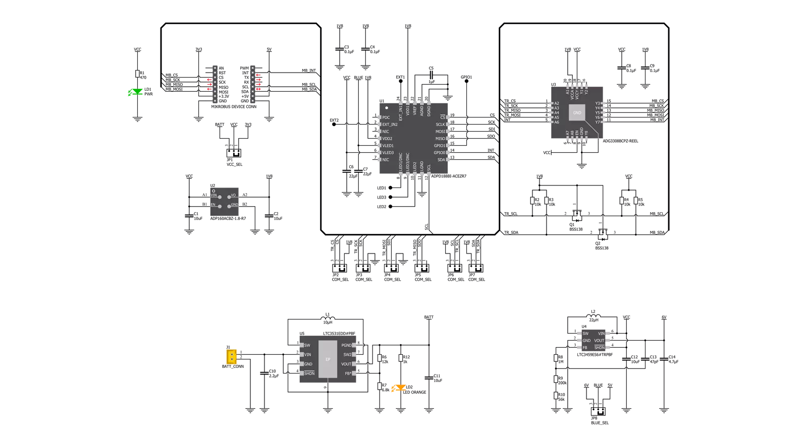
Smoke 2 Click is based on the ADPD188BI, a complete photometric system for smoke detection using optical dual-wavelength technology from Analog Devices. The module combines the dual photodetector with two separate LEDs and a mixed-signal photometric front-end ASIC. It prevents light from going directly from the LED to the photodiode without entering the smoke detection chamber. The dual-wavelength combination in a scattering measurement, a 470nm blue LED and an 850nm IR LED, allows particle size discrimination between different types of smoke, dust, or steam. The core circuitry stimulates the LEDs and measures the corresponding optical return signals. This integrated solution enables low power and reduces false smoke alarms in harsh environments due to dust, steam, and other nuisance sources. The smoke chamber 28800X is designed to be used with the ADPD188BI and minimize background response while controlling the environment around the ADPD188BI module by limiting dust accumulation and keeping out insects. The ADPD188BI registers a positive signal due to light scattering from the smoke chamber. Although the smoke chamber minimizes this positive signal, there is a nonzero response in the absence of smoke. When using a smoke chamber, this background response must be accounted for if you want to accurately measure the level of particles present in the smoke chamber. The ADPD188BI operates in three modes: Standby, Program, or Normal Sampling Mode. Standby Mode is a power-saving mode in which data collection does not occur, while the Program
Mode configures and program registers. During regular operation, the ADPD188BI pulses light and collects data, and in this mode, power consumption depends on the pulse count and data rate. Besides, the ADPD188BI also requires a supply voltage of 1.8V to work regularly. Therefore, a small regulating LDO, the ADP160 from Analog Devices, provides a 1.8V out of 3.3V mikroBUS™ rail, or optionally, from a battery power source. The output from the LDO regulator provides a needed voltage for one side of the ADG3308, a bidirectional level translator containing eight bidirectional channels from Analog Devices, while the voltage for the other side of the level translator is delivered from the VCC SEL jumper. Also, this Click board™ may be battery-powered, indicated via an LED indicator labeled as BATT, and used as a stand-alone device. It has LTC3531, a synchronous buck-boost DC/DC converter also from Analog Devices. It allows battery voltage to be converted to 3.3V and used in a selection of voltage needed to be converted by ADP160 to supply ADPD188BI. Smoke 2 Click provides the possibility of using both I2C and SPI serial interfaces, although only one is allowed at any given time in the actual application. All internal registers of the ADPD188BI are accessed through the selected communications interface. I2C supports Fast mode with data transfer of 400 kbps, while the SPI interface supports frequency up to 10MHz. This selection can be performed by positioning SMD jumpers labeled COMM SEL to an appropriate position. Note that all the jumpers must be lined to the same side, or the Click board™ may become unresponsive. Additionally, test points,
located in the upper part on the top side of the board, for pins EXT_IN1, EXT_IN2, and GPIO1 allow users to plug in external sensors like thermistors into the EXT pins and to use the GPIO1 pin for some digital functionality. The EXT_IN1 and EXT_IN2 pins are also current inputs that can be connected to external sensors. A voltage source can be connected to the EXT_IN1 and EXT_IN2 pins through a series resistance, effectively converting the voltage into a current. Other test points for LED1, LED2, and LED3 pins can be found under the smoke chamber on the top side of the board if users want to plug in their LEDs and not use the internal LEDs. The user also has the option to select the voltage for the blue LED of the ADPD188BI, which can be selected via the BLUE SEL jumper to analyze the characteristics with the recommended and maximum values. This diode can be powered by a maximum of 6V achieved by LTC3459 from Analog Devices. Optionally, the Smoke 2 Click board™, in addition to the mikroBUS™ power supply, can also be powered from an external battery. The battery power supply section is designed to power ADPD188BI and fulfill the demand for a complete solution, including the microcontroller and short-range radio power needs. This Click board™ can operate with either 3.3V or 5V logic voltage levels selected via the VCC SEL jumper. This way, both 3.3V and 5V capable MCUs can use the communication lines properly. Also, this Click board™ comes equipped with a library containing easy-to-use functions and an example code that can be used as a reference for further development.

Features overview
Development board
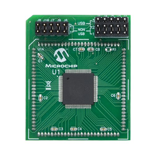
Explorer 16/32 development board is a flexible and convenient development, demonstration, and testing platform for 16-bit PIC24 MCUs, dsPIC® DSCs, and 32-bit PIC32 MCUs from Microchip Technology. It features all the necessary hardware to develop and debug a complete embedded application. The board accepts Processor Plug-In Modules (PIMs) designed for the Explorer 16 or Explorer 16/32 development board for easy device swapping. In addition to the hardware features provided by the board, hardware expansion is possible through the use of PICtail™ Plus
daughter cards and mikroBUS™ accessory boards. Coupled with the integrated PICkit™-On-Board (PKOB), MPLAB ICD In-Circuit Debugger real-time debug facilities enable faster evaluation and prototyping of applications. This development board supports all the Explorer PIMs. However, not all PIMs are supported by the PKOB. To check the list of supported and unsupported PIMs, refer to the PICkit™ On-Board 3 (PKOB3) Support List. For PIMs not on the PKOB3 support list, use the JP1 or J14 connectors to program the device with a newer generation programming tool. Explorer 16/32
development board offers only the main board, allowing customization of the other necessary components. Choose your PIM based on MCUs and DSCs under consideration from a wide range of Processor Plug-In Modules. This board is optimal for customers migrating from Classic Explorer 16 to the new Explorer 16/32 platform, while all the necessary additional components like Processor Plug-In Modules and PICtail™ Plus Daughter Boards are already available.

Microcontroller Overview
MCU Card / MCU
Architecture
dsPIC
MCU Memory (KB)
512
Silicon Vendor
Microchip
Pin count
100
RAM (Bytes)
53248
Used MCU Pins
mikroBUS™ mapper
Take a closer look
Click board™ Schematic
Step by step
Project assembly

Start by selecting your development board and Click board™. Begin with the Explorer 16/32 development board as your development board.


Software Support
Library Description
This library contains API for Smoke 2 Click driver.
Key functions:
smoke2_get_int_pin- This function eget state of int pin of Smoke 2 click board.smoke2_write_data- This function is generic for writing data to register of Smoke 2 click board.smoke2_read_data- This function is generic for reading data from registar of Smoke 2 click board.
Open Source
Code example
The complete application code and a ready-to-use project are available through the NECTO Studio Package Manager for direct installation in the NECTO Studio. The application code can also be found on the MIKROE GitHub account.
/*!
 * @file main.c
 * @brief Smoke2 Click example
 *
 * # Description
 * This example is made to see how Smoke 2 Clicks work. The purpose of this example is that,
 * depending on the way we choose, it collects data from the external environment about smoke,
 * processes it, and prints it via the UART terminal.
 *
 * The demo application is composed of two sections :
 *
 * ## Application Init
 * Initialization of communication modules, additional pins, Mapping pins and configures
 * device for measurement.
 *
 * ## Application Task
 * Example shows module working depending on example mode. We can choose between:
 * EXAMPLE_MODE_PROXIMITY and EXAMPLE_MODE_SMOKE.
 *
 * Additional Functions :
 * - void smoke_example ( smoke2_t *ctx ) - Example checks if sensor data goes over threshold set.
 * - void proximity_example ( void ) - Reads sensor data and logs it.
 *
 * @author Jelena Milosavljevic
 *
 */

#include "board.h"
#include "log.h"
#include "smoke2.h"

static smoke2_t smoke2;
static log_t logger;

#define EXAMPLE_MODE_SMOKE      0
#define EXAMPLE_MODE_PROXIMITY  1

#define EXAMPLE_MODE            EXAMPLE_MODE_SMOKE

/**
 * @brief Smoke 2 Smoke example.
 * @details This function checks if sensor data is gone over thershold set.
 */
void smoke_example ( smoke2_t *ctx );

/**
 * @brief Smoke 2 Proximity example.
 * @details This function reads sensor data and logs it.
 */
void proximity_example ( void );

void application_init ( void )
{
    log_cfg_t log_cfg;            /**< Logger config object. */
    smoke2_cfg_t smoke2_cfg;      /**< Click config object. */

    /**
     * Logger initialization.
     * Default baud rate: 115200
     * Default log level: LOG_LEVEL_DEBUG
     * @note If USB_UART_RX and USB_UART_TX
     * are defined as HAL_PIN_NC, you will
     * need to define them manually for log to work.
     * See @b LOG_MAP_USB_UART macro definition for detailed explanation.
     */
    LOG_MAP_USB_UART( log_cfg );
    log_init( &logger, &log_cfg );
    log_info( &logger, " Application Init " );

    // Click initialization.
    smoke2_cfg_setup( &smoke2_cfg );
    SMOKE2_MAP_MIKROBUS( smoke2_cfg, MIKROBUS_1 );
    err_t init_flag  = smoke2_init( &smoke2, &smoke2_cfg );
    if ( ( I2C_MASTER_ERROR == init_flag ) || ( SPI_MASTER_ERROR == init_flag ) )
    {
        log_error( &logger, " Application Init Error. " );
        log_info( &logger, " Please, run program again... " );
        for ( ; ; );
    }

    smoke2_soft_reset( &smoke2 );
    smoke2_set_mode( &smoke2, SMOKE2_MODE_IDLE );

    uint16_t devid = smoke2_read_data( &smoke2, SMOKE2_REG_DEVID );
    log_printf( &logger, ">> ID:  0x%.2X\r\n", ( uint16_t ) ( devid & 0xFF ) );
    log_printf( &logger, ">> REV: 0x%.2X\r\n", ( uint16_t ) ( ( devid >> 8 ) & 0xFF ) );
    Delay_ms ( 1000 );

    log_printf( &logger, ">> Configuration <<\r\n" );
    smoke2_default_cfg( &smoke2 );
    Delay_ms ( 1000 );

#if ( EXAMPLE_MODE == EXAMPLE_MODE_SMOKE )
    log_printf( &logger, ">> SMOKE MODE <<\r\n" );
    log_printf( &logger, ">> Calibration <<\r\n" );
    uint16_t calib_data = smoke2_smoke_calibration( &smoke2, 500 );
    log_printf( &logger, ">> Calibration data: %u\r\n", calib_data );
#elif ( EXAMPLE_MODE == EXAMPLE_MODE_PROXIMITY )
    log_printf( &logger, ">> PROXIMITY MODE <<\r\n" );
#endif
    log_info( &logger, " Application Task " );
}

void application_task ( void )
{
#if ( EXAMPLE_MODE == EXAMPLE_MODE_SMOKE )
    smoke_example( &smoke2 );
#elif ( EXAMPLE_MODE == EXAMPLE_MODE_PROXIMITY )
    proximity_example( );
#endif
}

int main ( void )
{
    /* Do not remove this line or clock might not be set correctly. */
    #ifdef PREINIT_SUPPORTED
    preinit();
    #endif

    application_init( );

    for ( ; ; )
    {
        application_task( );
    }

    return 0;
}

void smoke_example ( smoke2_t *ctx )
{
    static uint8_t last_state = 0;
    uint8_t smoke_detected = smoke2_check_smoke( &smoke2 );
    if ( last_state != smoke_detected )
    {
        if ( SMOKE2_SMOKE_DETECTED == smoke_detected )
        {
            log_printf( &logger, ">> SMOKE_DETECTED <<\r\n" );
        }
        else if ( SMOKE2_SMOKE_NOT_DETECTED == smoke_detected )
        {
            log_printf( &logger, ">> SMOKE_CLEAR <<\r\n" );
        }
        else
        {
            log_printf( &logger, ">> ERROR <<\r\n" );
            for( ; ; );
        }
        last_state = smoke_detected;
    }
}

void proximity_example ( void )
{
    uint16_t sens_data = 0;
    uint8_t fifo_int = 0;
    uint8_t slot_a_int = 0;
    uint8_t slot_b_int = 0;
    if ( 0 == smoke2_get_int_pin( &smoke2 ) )
    {
        smoke2_get_int( &smoke2, &fifo_int, &slot_a_int, &slot_b_int );
        if ( 0 != slot_a_int )
        {
            sens_data = smoke2_read_sens_data( &smoke2, SMOKE2_SLOT_A, SMOKE2_CHN_1 );
            log_printf( &logger, ">> DATA A: %d\r\n", sens_data );
            slot_a_int = 0;
            Delay_ms ( 100 );
        }
        if ( 0 != slot_b_int )
        {
            sens_data = smoke2_read_sens_data( &smoke2, SMOKE2_SLOT_B, SMOKE2_CHN_1 );
            log_printf( &logger, ">> DATA B: %d\r\n", sens_data );
            slot_b_int = 0;
            Delay_ms ( 100 );
        }
        if ( 0 != fifo_int )
        {
            log_printf( &logger, " \r\n", fifo_int );
            for ( uint8_t fifo_cnt = 0; fifo_cnt < fifo_int; fifo_cnt++ )
            {
                sens_data = smoke2_read_data( &smoke2, SMOKE2_REG_FIFO_ACCESS );
                log_printf( &logger, ">> FIFO: %d\r\n", sens_data );
            }
            Delay_ms ( 100 );
        }
    }
}

// ------------------------------------------------------------------------ END
Additional Support
Resources
Category:Optical


