Upgrade current measurements to unprecedented levels of accuracy with MCS1806 and dsPIC33EP512MU810
Hall effect innovation for seamless AC/DC current detection

Published Nov 15, 2023
Click board™
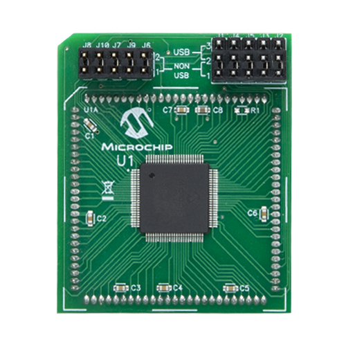
Hall Current 18 Click
Dev. board
Explorer 16/32 development board
Compiler
NECTO Studio
MCU
dsPIC33EP512MU810
Step into a new era of current measurement reliability with our Hall effect sensors, designed to meet the demands of modern industries by providing non-intrusive, high-precision monitoring for both AC and DC currents.
A
A
Hardware Overview
How does it work?
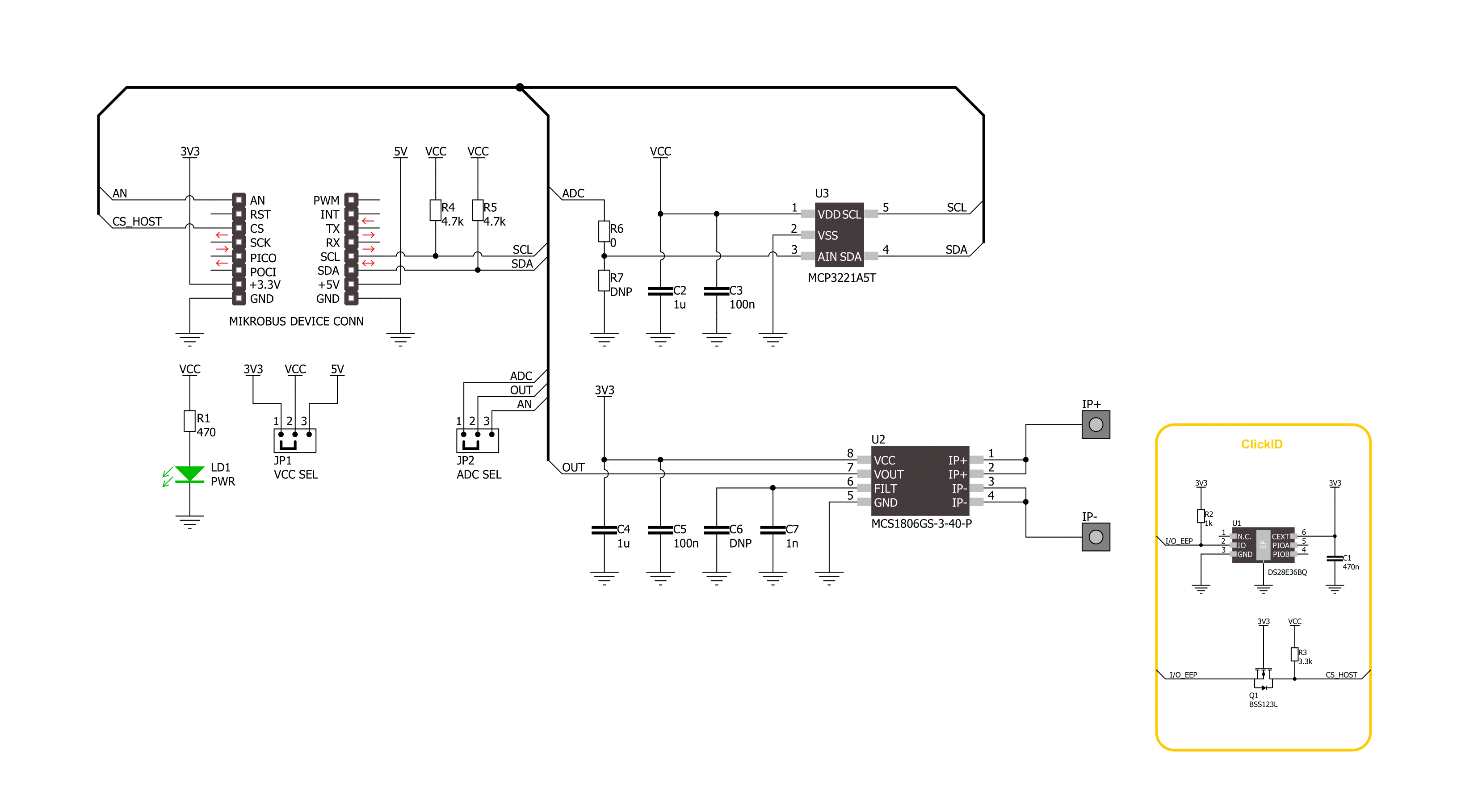
Hall Current 18 Click is based on the MCS1806, an isolated Hall-effect current sensor from MPS. Its primary conductor has low resistance and allows current to flow close to the high-accuracy Hall-effect sensors. The current generates a magnetic field that is sensed at two different points by the integrated Hall-effect transducers. The difference in the magnetic field between those two points is converted into a voltage proportional to the applied current. As a low stable offset, a spinning current technique is used. The MCS1806 outputs an analog signal, which on this board™ can be read in a digital form. For that purpose, Hall Current 18 Click features the MCP3221, a successive
approximation A/D converter with a 12-bit resolution from Microchip. The onboard OUT SEL jumper allows you to choose between the analog and digital output of the sensor. The MCP3221 is selected by default. This Click board™ should be connected in series with the load. Two onboard terminal connectors measure the current, one terminal block for the positive and the other for the negative current input. Hall Current 18 Click can use an analog output to allow the host MCU to read the data as analog values. In addition, over the MCP3221 and standard 2-Wire I2C interface, it can allow the host MCU to read data in a digital form and 12-bit resolution. Data can be transferred at
rates of up to 100kbit/s in the Standard and 400kbit/s in the Fast Mode. Also, maximum sample rates of 22.3kSPS with the MCP3221 are possible in a Continuous-Conversion Mode with a clock rate of 400kHz. This Click board™ can operate with either 3.3V or 5V logic voltage levels selected via the VCC SEL jumper. This way, both 3.3V and 5V capable MCUs can use the communication lines properly. Also, this Click board™ comes equipped with a library containing easy-to-use functions and an example code that can be used as a reference for further development.


Features overview
Development board
Explorer 16/32 development board is a flexible and convenient development, demonstration, and testing platform for 16-bit PIC24 MCUs, dsPIC® DSCs, and 32-bit PIC32 MCUs from Microchip Technology. It features all the necessary hardware to develop and debug a complete embedded application. The board accepts Processor Plug-In Modules (PIMs) designed for the Explorer 16 or Explorer 16/32 development board for easy device swapping. In addition to the hardware features provided by the board, hardware expansion is possible through the use of PICtail™ Plus
daughter cards and mikroBUS™ accessory boards. Coupled with the integrated PICkit™-On-Board (PKOB), MPLAB ICD In-Circuit Debugger real-time debug facilities enable faster evaluation and prototyping of applications. This development board supports all the Explorer PIMs. However, not all PIMs are supported by the PKOB. To check the list of supported and unsupported PIMs, refer to the PICkit™ On-Board 3 (PKOB3) Support List. For PIMs not on the PKOB3 support list, use the JP1 or J14 connectors to program the device with a newer generation programming tool. Explorer 16/32
development board offers only the main board, allowing customization of the other necessary components. Choose your PIM based on MCUs and DSCs under consideration from a wide range of Processor Plug-In Modules. This board is optimal for customers migrating from Classic Explorer 16 to the new Explorer 16/32 platform, while all the necessary additional components like Processor Plug-In Modules and PICtail™ Plus Daughter Boards are already available.

Microcontroller Overview
MCU Card / MCU
Architecture
dsPIC
MCU Memory (KB)
512
Silicon Vendor
Microchip
Pin count
100
RAM (Bytes)
53248
Used MCU Pins
mikroBUS™ mapper
Take a closer look
Click board™ Schematic
Step by step
Project assembly

Start by selecting your development board and Click board™. Begin with the Explorer 16/32 development board as your development board.


Track your results in real time
Application Output
1. Application Output - In Debug mode, the 'Application Output' window enables real-time data monitoring, offering direct insight into execution results. Ensure proper data display by configuring the environment correctly using the provided tutorial.

2. UART Terminal - Use the UART Terminal to monitor data transmission via a USB to UART converter, allowing direct communication between the Click board™ and your development system. Configure the baud rate and other serial settings according to your project's requirements to ensure proper functionality. For step-by-step setup instructions, refer to the provided tutorial.

3. Plot Output - The Plot feature offers a powerful way to visualize real-time sensor data, enabling trend analysis, debugging, and comparison of multiple data points. To set it up correctly, follow the provided tutorial, which includes a step-by-step example of using the Plot feature to display Click board™ readings. To use the Plot feature in your code, use the function: plot(*insert_graph_name*, variable_name);. This is a general format, and it is up to the user to replace 'insert_graph_name' with the actual graph name and 'variable_name' with the parameter to be displayed.

Software Support
Library Description
This library contains API for Hall Current 18 Click driver.
Key functions:
hallcurrent18_read_current- Hall Current 18 read current function.hallcurrent18_read_voltage- Hall Current 18 read voltage level function.allcurrent18_read_raw_adc- Hall Current 18 read raw ADC value function.
Open Source
Code example
The complete application code and a ready-to-use project are available through the NECTO Studio Package Manager for direct installation in the NECTO Studio. The application code can also be found on the MIKROE GitHub account.
/*!
* @file main.c
* @brief Hall Current 18 Click Example.
*
* # Description
* This example demonstrates the use of Hall Current 18 Click board™
* by reading and displaying the current measurements.
*
* The demo application is composed of two sections :
*
* ## Application Init
* The initialization of SPI module and log UART.
* After driver initialization, the app sets the default configuration
* and set the zero voltage reference.
*
* ## Application Task
* The demo application reads the current measurements [A] and displays the results.
* Results are being sent to the UART Terminal, where you can track their changes.
*
* @author Nenad Filipovic
*
*/
#include "board.h"
#include "log.h"
#include "hallcurrent18.h"
static hallcurrent18_t hallcurrent18; /**< Hall Current 18 Click driver object. */
static log_t logger; /**< Logger object. */
void application_init ( void )
{
log_cfg_t log_cfg; /**< Logger config object. */
hallcurrent18_cfg_t hallcurrent18_cfg; /**< Click config object. */
/**
* Logger initialization.
* Default baud rate: 115200
* Default log level: LOG_LEVEL_DEBUG
* @note If USB_UART_RX and USB_UART_TX
* are defined as HAL_PIN_NC, you will
* need to define them manually for log to work.
* See @b LOG_MAP_USB_UART macro definition for detailed explanation.
*/
LOG_MAP_USB_UART( log_cfg );
log_init( &logger, &log_cfg );
log_info( &logger, " Application Init " );
// Click initialization.
hallcurrent18_cfg_setup( &hallcurrent18_cfg );
HALLCURRENT18_MAP_MIKROBUS( hallcurrent18_cfg, MIKROBUS_1 );
err_t init_flag = hallcurrent18_init( &hallcurrent18, &hallcurrent18_cfg );
if ( ( ADC_ERROR == init_flag ) || ( I2C_MASTER_ERROR == init_flag ) )
{
log_error( &logger, " Communication init." );
for ( ; ; );
}
if ( HALLCURRENT18_ERROR == hallcurrent18_default_cfg ( &hallcurrent18 ) )
{
log_error( &logger, " Default configuration." );
for ( ; ; );
}
Delay_ms ( 100 );
log_printf( &logger, " Turn off the load current in the following 5 sec.\r\n" );
Delay_ms ( 1000 );
Delay_ms ( 1000 );
Delay_ms ( 1000 );
Delay_ms ( 1000 );
Delay_ms ( 1000 );
if ( HALLCURRENT18_OK == hallcurrent18_set_zero_ref( &hallcurrent18 ) )
{
log_printf( &logger, " Process complete!\r\n");
}
else
{
log_error( &logger, " Zero reference." );
for ( ; ; );
}
log_info( &logger, " Application Task " );
Delay_ms ( 100 );
}
void application_task ( void )
{
float current = 0;
if ( HALLCURRENT18_OK == hallcurrent18_read_current ( &hallcurrent18, ¤t ) )
{
log_printf( &logger, " Current : %.2f [A]\r\n", current );
Delay_ms ( 1000 );
}
}
int main ( void )
{
/* Do not remove this line or clock might not be set correctly. */
#ifdef PREINIT_SUPPORTED
preinit();
#endif
application_init( );
for ( ; ; )
{
application_task( );
}
return 0;
}
// ------------------------------------------------------------------------ END


