Experience the future of magnetic field detection with ALS31300 and PIC18F46K40
A new dimension of insight: Discover our 3D magnetic sensor's X, Y, and Z capabilities

Published Sep 28, 2023
Click board™
3D Hall 9 Click
Dev. board
EasyPIC v8
Compiler
NECTO Studio
MCU
PIC18F46K40
From industrial automation to scientific research, our 3D magnetic field strength detector opens doors to endless possibilities, ensuring accurate measurements across all three dimensions
A
A
Hardware Overview
How does it work?
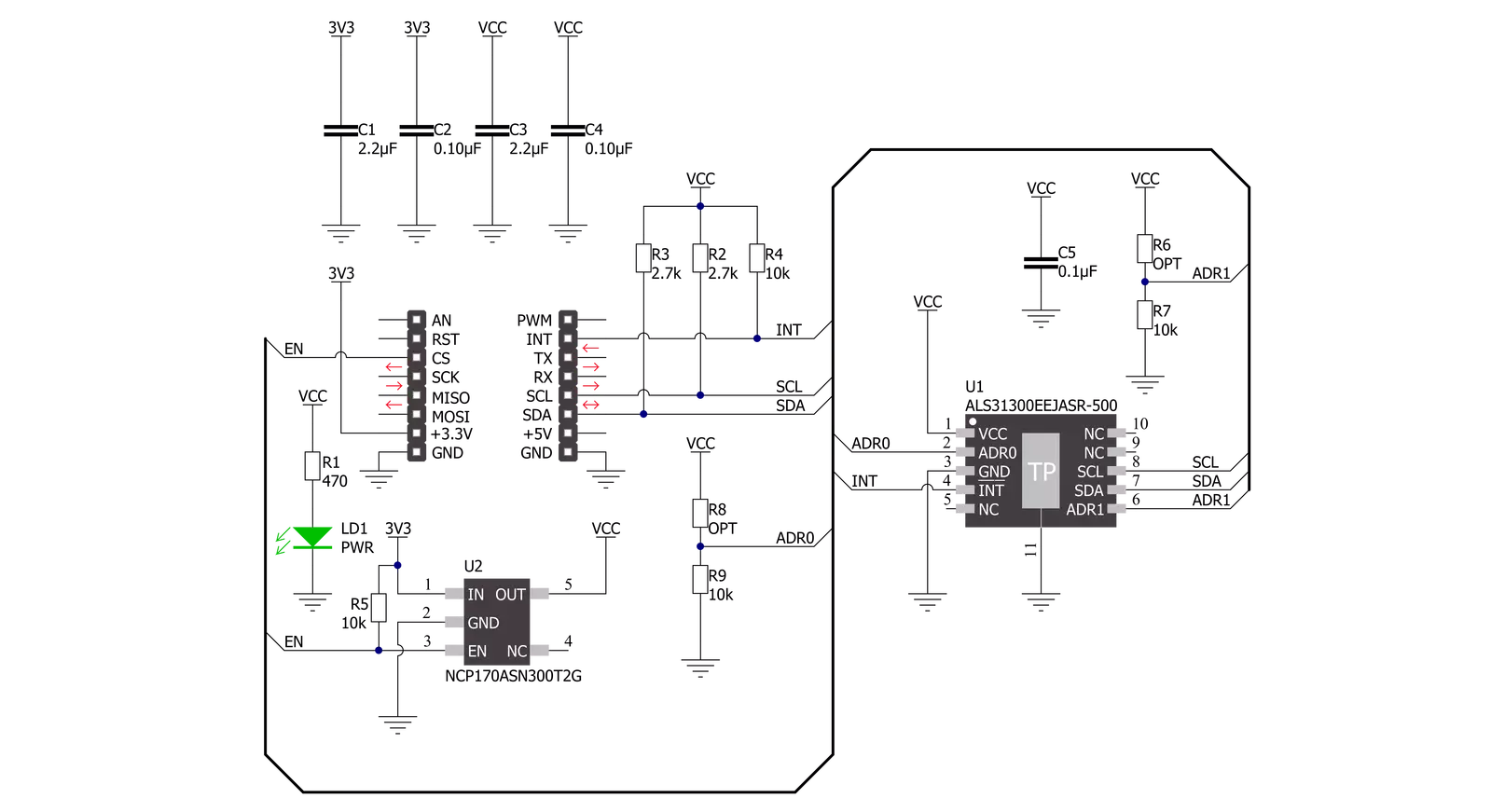
3D Hall 9 Click is based on the ALS31300, a 3D linear Hall-effect sensor used to detect the strength of a magnetic field in all three dimensions (X, Y, and Z axes) from Allegro Microsystems. The ALS31300 provides a 12-bit digital output value proportional to the magnetic field generally applied to any of the Hall elements alongside a 12-bit temperature output representing the junction temperature of the IC. The quiescent output value (zero magnetic fields used) is at mid-scale. The ALS31300 has a factory-programmed sensitivity range of ±500G, suitable for 3D linear or 2D angle sensing applications. Power management on the ALS31300 is user-selectable and highly configurable, allowing for system-level optimization of current consumption and performance. It supports three power modes: Active, Sleep, and Low-Power Duty Cycle Mode (LPDCM). The operating mode of the ALS31300 will
be determined by the selected proper value of the 0x27 register. More information on the operational modes can be found in the attached datasheet. 3D Hall 9 Click communicates with MCU using the standard I2C 2-Wire interface to read data and configure settings, supporting Standard Mode operation with a clock frequency of 100kHz and Fast Mode up to 400kHz. It provides data in digital format of 12 bits corresponding to the magnetic field measured in each X, Y, and Z axes. The ALS31300 also requires a supply voltage of 3V to work regularly. Therefore, a small LDO regulator, NCP170 from ON Semiconductor, provides a 3V out of mikroBUS™ 3V3 power rail. This Click board™ also uses the Enable pin labeled as EN and routed to the CS pin of the mikroBUS™ socket to optimize power consumption, used for its power ON/OFF purposes. The ALS31300 provides the ability to set different I2C slave addresses (16
unique addresses) by populating the appropriate resistors (R8 and R6), thus forming a voltage divider with a voltage value that corresponds to the desired I2C address. It also possesses an additional interrupt signal, routed on the INT pin of the mikroBUS™ socket. It integrates the detection and reporting of significant changes in an applied magnetic field (independently turned on or off for each of the three axes). An interrupt event is initiated when the applied magnetic field forces the ADC output to a value greater than or equal to the user-programmed threshold. This Click board™ can be operated only with a 3.3V logic voltage level. The board must perform appropriate logic voltage level conversion before using MCUs with different logic levels. Also, it comes equipped with a library containing functions and an example code that can be used as a reference for further development.


Features overview
Development board
EasyPIC v8 is a development board specially designed for the needs of rapid development of embedded applications. It supports many high pin count 8-bit PIC microcontrollers from Microchip, regardless of their number of pins, and a broad set of unique functions, such as the first-ever embedded debugger/programmer. The development board is well organized and designed so that the end-user has all the necessary elements, such as switches, buttons, indicators, connectors, and others, in one place. Thanks to innovative manufacturing technology, EasyPIC v8 provides a fluid and immersive working experience, allowing access anywhere and under any
circumstances at any time. Each part of the EasyPIC v8 development board contains the components necessary for the most efficient operation of the same board. In addition to the advanced integrated CODEGRIP programmer/debugger module, which offers many valuable programming/debugging options and seamless integration with the Mikroe software environment, the board also includes a clean and regulated power supply module for the development board. It can use a wide range of external power sources, including a battery, an external 12V power supply, and a power source via the USB Type-C (USB-C) connector.
Communication options such as USB-UART, USB DEVICE, and CAN are also included, including the well-established mikroBUS™ standard, two display options (graphical and character-based LCD), and several different DIP sockets. These sockets cover a wide range of 8-bit PIC MCUs, from the smallest PIC MCU devices with only eight up to forty pins. EasyPIC v8 is an integral part of the Mikroe ecosystem for rapid development. Natively supported by Mikroe software tools, it covers many aspects of prototyping and development thanks to a considerable number of different Click boards™ (over a thousand boards), the number of which is growing every day.

Microcontroller Overview
MCU Card / MCU
Architecture
PIC
MCU Memory (KB)
64
Silicon Vendor
Microchip
Pin count
40
RAM (Bytes)
3728
Used MCU Pins
mikroBUS™ mapper
Take a closer look
Click board™ Schematic
Step by step
Project assembly

Start by selecting your development board and Click board™. Begin with the EasyPIC v8 as your development board.


Software Support
Library Description
This library contains API for 3D Hall 9 Click driver.
Key functions:
c3dhall9_write_register- This function writes a desired data to the selected register by using I2C serial interface.c3dhall9_read_register- This function reads a desired data from the selected register by using I2C serial interface.c3dhall9_read_data- This function reads new data which consists of X, Y, and Z axis values in Gauss, and temperature in Celsius. It also calculates the angles between all axes in Degrees based on the raw axes data read.
Open Source
Code example
The complete application code and a ready-to-use project are available through the NECTO Studio Package Manager for direct installation in the NECTO Studio. The application code can also be found on the MIKROE GitHub account.
/*!
 * @file main.c
 * @brief 3DHall9 Click example
 *
 * # Description
 * This example demonstrates the use of 3D Hall 9 Click board by reading the magnetic
 * flux density from 3 axes as well as the angles between axes and the sensor temperature.
 *
 * The demo application is composed of two sections :
 *
 * ## Application Init
 * Initializes the driver and the Click board.
 *
 * ## Application Task
 * Reads the new data from the sensor approximately every 300ms and displays
 * the measurement values on the USB UART.
 *
 * @author Stefan Filipovic
 *
 */

#include "board.h"
#include "log.h"
#include "c3dhall9.h"

static c3dhall9_t c3dhall9;
static log_t logger;

void application_init ( void )
{
    log_cfg_t log_cfg;  /**< Logger config object. */
    c3dhall9_cfg_t c3dhall9_cfg;  /**< Click config object. */

    /**
     * Logger initialization.
     * Default baud rate: 115200
     * Default log level: LOG_LEVEL_DEBUG
     * @note If USB_UART_RX and USB_UART_TX
     * are defined as HAL_PIN_NC, you will
     * need to define them manually for log to work.
     * See @b LOG_MAP_USB_UART macro definition for detailed explanation.
     */
    LOG_MAP_USB_UART( log_cfg );
    log_init( &logger, &log_cfg );
    log_info( &logger, " Application Init " );

    // Click initialization.
    c3dhall9_cfg_setup( &c3dhall9_cfg );
    C3DHALL9_MAP_MIKROBUS( c3dhall9_cfg, MIKROBUS_1 );
    if ( I2C_MASTER_ERROR == c3dhall9_init( &c3dhall9, &c3dhall9_cfg ) )
    {
        log_error( &logger, " Communication init." );
        for ( ; ; );
    }

    if ( C3DHALL9_ERROR == c3dhall9_default_cfg ( &c3dhall9 ) )
    {
        log_error( &logger, " Default configuration." );
        for ( ; ; );
    }

    log_info( &logger, " Application Task " );
}

void application_task ( void )
{
    c3dhall9_data_t sensor_data;

    if ( C3DHALL9_OK == c3dhall9_read_data ( &c3dhall9, &sensor_data ) )
    {
        log_printf( &logger, " X-axis: %.1f Gauss\r\n", sensor_data.x_axis );
        log_printf( &logger, " Y-axis: %.1f Gauss\r\n", sensor_data.y_axis );
        log_printf( &logger, " Z-axis: %.1f Gauss\r\n", sensor_data.z_axis );
        log_printf( &logger, " Angle XY: %.1f Degrees\r\n", sensor_data.angle_xy );
        log_printf( &logger, " Angle XZ: %.1f Degrees\r\n", sensor_data.angle_xz );
        log_printf( &logger, " Angle YZ: %.1f Degrees\r\n", sensor_data.angle_yz );
        log_printf( &logger, " Temperature: %.2f Celsius\r\n\n", sensor_data.temperature );
        Delay_ms ( 300 );
    }
}

int main ( void )
{
    /* Do not remove this line or clock might not be set correctly. */
    #ifdef PREINIT_SUPPORTED
    preinit();
    #endif

    application_init( );

    for ( ; ; )
    {
        application_task( );
    }

    return 0;
}

// ------------------------------------------------------------------------ END
Additional Support
Resources
Category:Magnetic


