Step into the future of lighting control with AS7225 combined with PIC18F45K50
From sunsets to sunrises: Ambient light sensing for every mood
Published Sep 22, 2023
Click board™
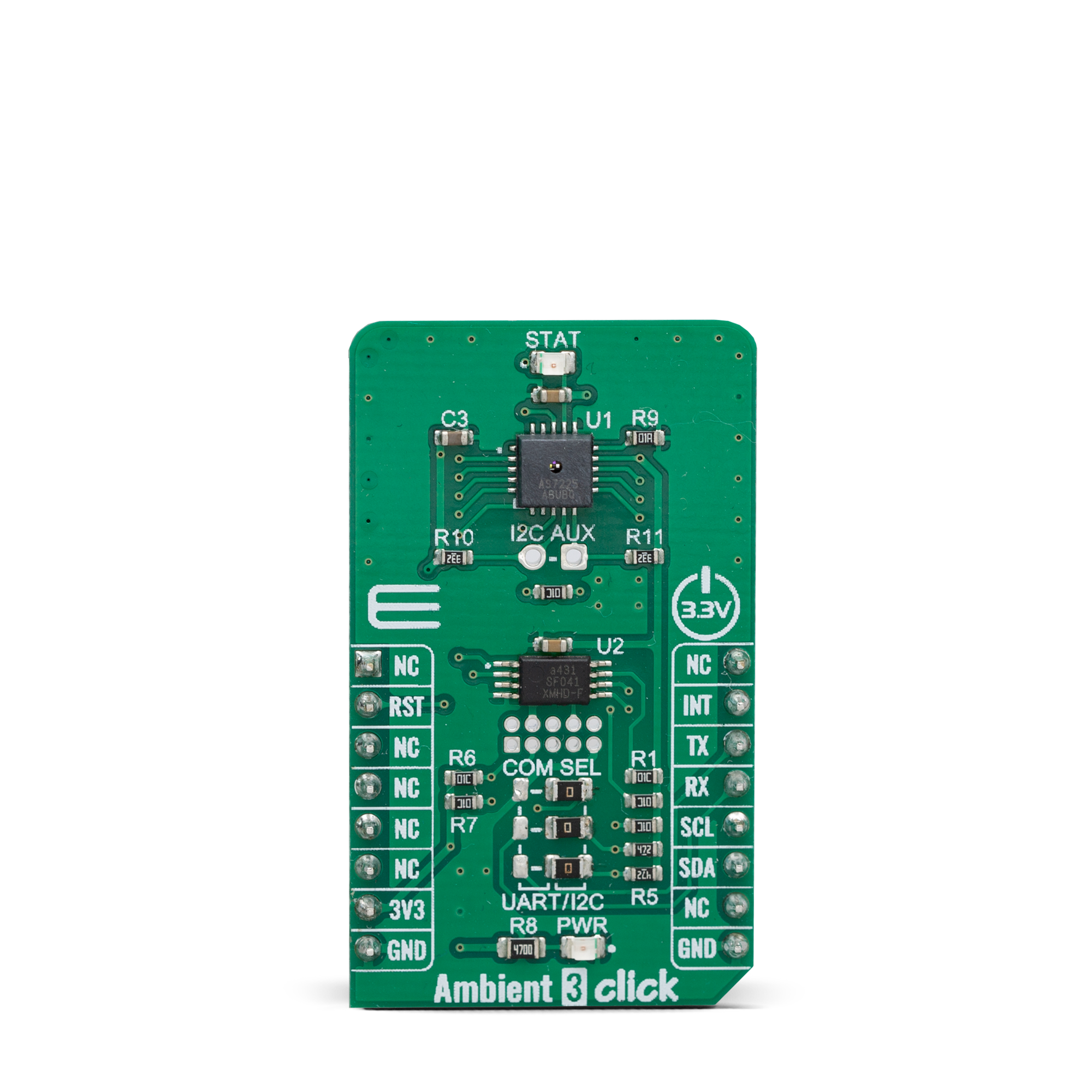
Ambient 3 Click
Dev. board
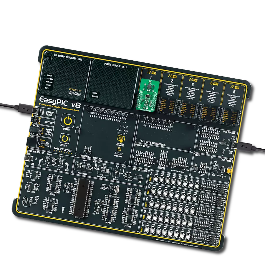
EasyPIC v8
Compiler
NECTO Studio
MCU
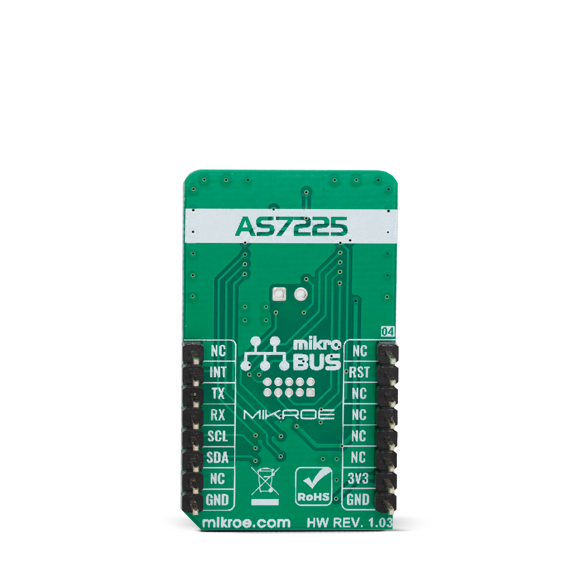
PIC18F45K50
Our cutting-edge ambient light intensity-sensing solution utilizes advanced photodetectors and algorithms to precisely measure and control light levels in real-time
A
A
Hardware Overview
How does it work?
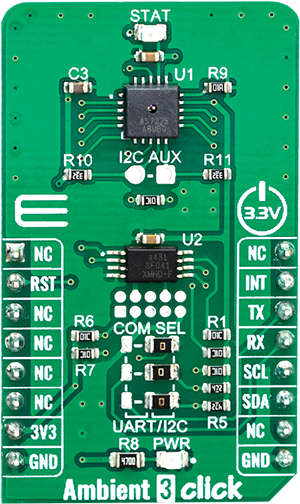
Ambient 3 Click is based on the AS7225, a calibrated XYZ chromatic smart lighting director with UART and I2C interfaces, from ams OSRAM. This sensor utilizes Standard observer tristimulus (XYZ) interference filters, which are applied to the Calibrated XYZ Chromatic Smart Lighting Director optical channels as part of the CMOS process. By utilizing a sensitive photo-diode, low noise amplifier, and a 16-bit A/D converter (ADC), this sensor can provide the data directly, with no need for complex calculations. Calibration is accomplished using standard white LEDs at a variety of CCTs to deliver high accuracy and eliminate the need for light-by-light calibration in most designs. A high dynamic range along with a linear response to different light sources, allows this sensor to be placed behind a dark glass or panels made of other semi-transparent materials. The AS7225 sensors registers are organized into seven main groups, which makes it very simple to configure and use. Even though, it comes with the mikroSDK compatible library, which simplifies the development even more. However, more detailed explanation of each command can be found in
the datasheet of the AS7225, if required. By using these registers, the user can configure the Click board™ and the equipped AS7225 sensor, fine-tuning it according to the requirements of the application. All the working parameters including the sensitivity, integration time, interrupt detection, persistence protection for the interrupt triggering, low and high threshold window for the interrupt, can all be set using these registers. Finally, the Ambient Light Sensing (ALS) result can be found here in calibrated sensor result register group. The user also can access to the raw value data and calibration coefficients by reading the appropriate registers. The data can be read or written in LSB/MSB format, using the 8-bit I2C interface. Register bits DATA_RDY give information about finished integration and calculation. An interrupt event will be generated, asserting this pin to a LOW logic level when new calculated PWM dimming percent values are available for the external MCU. If the interrupt register bit for either are enabled (RDY_INT = 1, PWM_INT =1) then when either of these activities become active, indicating available data, the INT
pin is pulled low in addition to setting the ready register bit(s). The INT Line is released when the appropriate control register (CONV_Control and/or DIR_ Control) is read. The interrupt pin is routed to the mikroBUS™ INT pin. The AS7225 initial setup and ongoing parameter storage is automatically done by software within the required external serial Flash memory, via SPI bus. Therefore, Ambient 3 click has AT25SF041-XMHD-T IC – a 4MB flash memory module onboard. The AS7225 contains a serial UART interface to connect to a flash memory The Click board™ is supported by the mikroSDK library, which contains functions for simplified development. The mikroSDK functions are well-documented, but there is still a need, the datasheet of the AS7225 offers listing of all the registers and their specific functions. This Click board™ can be operated only with a 3.3V logic voltage level. The board must perform appropriate logic voltage level conversion before using MCUs with different logic levels. Also, it comes equipped with a library containing functions and an example code that can be used as a reference for further development.
Features overview
Development board
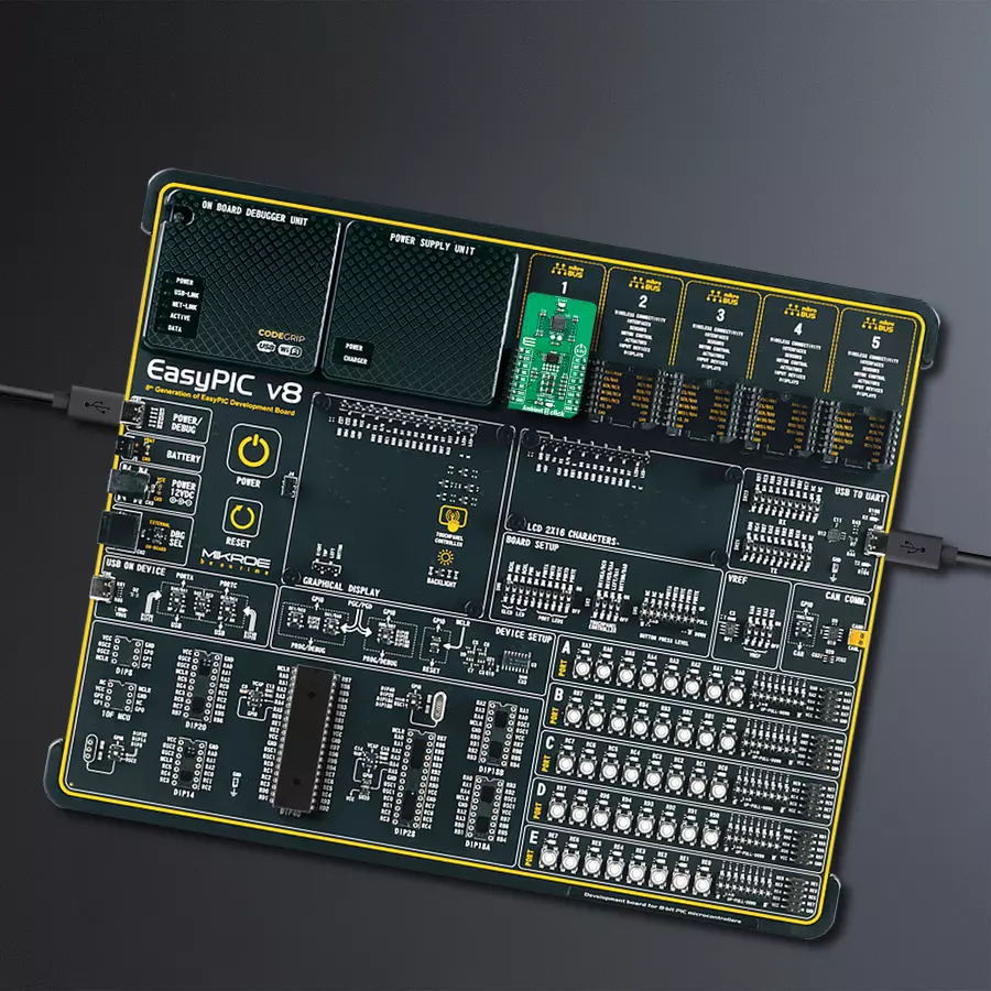
EasyPIC v8 is a development board specially designed for the needs of rapid development of embedded applications. It supports many high pin count 8-bit PIC microcontrollers from Microchip, regardless of their number of pins, and a broad set of unique functions, such as the first-ever embedded debugger/programmer. The development board is well organized and designed so that the end-user has all the necessary elements, such as switches, buttons, indicators, connectors, and others, in one place. Thanks to innovative manufacturing technology, EasyPIC v8 provides a fluid and immersive working experience, allowing access anywhere and under any
circumstances at any time. Each part of the EasyPIC v8 development board contains the components necessary for the most efficient operation of the same board. In addition to the advanced integrated CODEGRIP programmer/debugger module, which offers many valuable programming/debugging options and seamless integration with the Mikroe software environment, the board also includes a clean and regulated power supply module for the development board. It can use a wide range of external power sources, including a battery, an external 12V power supply, and a power source via the USB Type-C (USB-C) connector.
Communication options such as USB-UART, USB DEVICE, and CAN are also included, including the well-established mikroBUS™ standard, two display options (graphical and character-based LCD), and several different DIP sockets. These sockets cover a wide range of 8-bit PIC MCUs, from the smallest PIC MCU devices with only eight up to forty pins. EasyPIC v8 is an integral part of the Mikroe ecosystem for rapid development. Natively supported by Mikroe software tools, it covers many aspects of prototyping and development thanks to a considerable number of different Click boards™ (over a thousand boards), the number of which is growing every day.

Microcontroller Overview
MCU Card / MCU
Architecture
PIC
MCU Memory (KB)
32
Silicon Vendor
Microchip
Pin count
40
RAM (Bytes)
2048
Used MCU Pins
mikroBUS™ mapper
Take a closer look
Click board™ Schematic

Step by step
Project assembly

Start by selecting your development board and Click board™. Begin with the EasyPIC v8 as your development board.


Software Support
Library Description
This library contains API for Ambient 3 Click driver.
Key functions:
ambient3_get_device_temperature- ambient3_get_data_in_LUXambient3_get_data_in_LUX- This function reads data in LUX
Open Source
Code example
The complete application code and a ready-to-use project are available through the NECTO Studio Package Manager for direct installation in the NECTO Studio. The application code can also be found on the MIKROE GitHub account.
/*!
 * \file
 * \brief Ambient3 Click example
 *
 * # Description
 * This example demonstrates the use of Ambient 3 Click board.
 *
 * The demo application is composed of two sections :
 *
 * ## Application Init
 * Initializes the driver and logger.
 *
 * ## Application Task
 * Reads the device temperature, and daylight in LUX and logs results to USB UART each second.
 *
 * \author MikroE Team
 *
 */
// ------------------------------------------------------------------- INCLUDES

#include "board.h"
#include "log.h"
#include "ambient3.h"

// ------------------------------------------------------------------ VARIABLES

static ambient3_t ambient3;
static log_t logger;

static uint8_t temperature;
static uint16_t data_lux;

// ------------------------------------------------------ APPLICATION FUNCTIONS

void application_init ( void )
{
    log_cfg_t log_cfg;
    ambient3_cfg_t cfg;

    /**
     * Logger initialization.
     * Default baud rate: 115200
     * Default log level: LOG_LEVEL_DEBUG
     * @note If USB_UART_RX and USB_UART_TX
     * are defined as HAL_PIN_NC, you will
     * need to define them manually for log to work.
     * See @b LOG_MAP_USB_UART macro definition for detailed explanation.
     */
    LOG_MAP_USB_UART( log_cfg );
    log_init( &logger, &log_cfg );
    log_info( &logger, "---- Application Init ----" );

    //  Click initialization.

    ambient3_cfg_setup( &cfg );
    AMBIENT3_MAP_MIKROBUS( cfg, MIKROBUS_1 );
    ambient3_init( &ambient3, &cfg );
    ambient3_default_cfg( &ambient3 );
    Delay_ms ( 100 );
}

void application_task ( )
{
    temperature = ambient3_get_device_temperature( &ambient3 );
    log_printf( &logger, " - Device temperature in Celsius : %u\r\n", ( uint16_t ) temperature );

    data_lux = ambient3_get_data_in_lux( &ambient3 );
    log_printf( &logger, " - Light in LUX : %u\r\n", data_lux );
    log_printf( &logger, " --------------------\r\n" );

    Delay_ms ( 1000 );
}

int main ( void )
{
    /* Do not remove this line or clock might not be set correctly. */
    #ifdef PREINIT_SUPPORTED
    preinit();
    #endif

    application_init( );

    for ( ; ; )
    {
        application_task( );
    }

    return 0;
}


// ------------------------------------------------------------------------ END


