Unleashing the agility of DC motors with L99UDL01 and PIC18F47K42
Motor control made brilliantly simple
Published Jul 23, 2023
Click board™
H-Bridge 9 Click
Dev. board
EasyPIC v8
Compiler
NECTO Studio
MCU
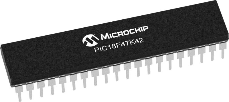
PIC18F47K42
Revolutionize your engineering project with tailored motor control solutions; unleash more than one DC motor with this solution!
A
A
Hardware Overview
How does it work?
H-Bridge 9 Click is based on the L99UDL01, a half-bridge driver PWM configurable and current-regulated from STMicroelectronics. The device contains six MOSFET half-bridge outputs and protection and diagnostic functions designed to improve safety and simplify the design. As a complete solution, this Click board™ replaces several separate motor drivers along with their associated analog and passive components, offering at the same time a more sophisticated functionality. The L99UDL01 can enter four different operating modes to control the working sequence: Normal mode, Sleep mode, Emergency override mode, and Standby mode as its default operation. In the Sleep mode, no-active circuitry is supplied, where logic is initialized but not operational. There is no function present in either mode to minimize the current consumption. Only wake-up circuitry is active in the Standby mode. Also, an emergency mode represents a crash override mechanism that will interrupt any current actuation command in progress and drive outputs
according to the programmed values in the command and configuration registers. Benefits are further enhanced by PWM control of the output current and sophisticated diagnostic functions that detect over-currents, line breaks, and short circuits to the battery and ground. The load-integrity tests can also be performed without activating the load. Also, programmable current limiting allows users to reduce the load, thereby increasing reliability. The output MOSFETs are fully protected with low RDS(ON) values, increasing energy efficiency and facilitating thermal management. The L99UDL01 communicates with MCU using the standard SPI serial interface with a maximum frequency of 4MHz, supporting the most common SPI mode, SPI Mode 0. It also features an interrupt function labeled as DO and routed to the INT pin of the mikroBUS™ socket that provides the host processor with a real-time fault indication. Besides an interrupt pin, Enable pin labeled as ENO and routed to the PWM pin of the mikroBUS™ socket enables the output
functionality while held high and turns off the outputs when kept low. This pin can also be used to initiate an output timed actuation, based on programmed parameters, on a rising edge. The H-Bridge 9 Click supports an external power supply for the L99UDL01, which can be connected to the input terminal labeled as VS and should be within the range of 6V to 18V, while the DC motor coils can be connected to the terminals labeled from O1 to O6. These outputs are configured as switching drivers incorporating active re-circulation to minimize power dissipation. It also has over-current protection, under-current detection, and OFF-state diagnostics. This Click board™ can operate with either 3.3V or 5V logic voltage levels selected via the VCC SEL jumper. This way, both 3.3V and 5V capable MCUs can use the communication lines properly. However, the Click board™ comes equipped with a library containing easy-to-use functions and an example code that can be used, as a reference, for further development.

Features overview
Development board
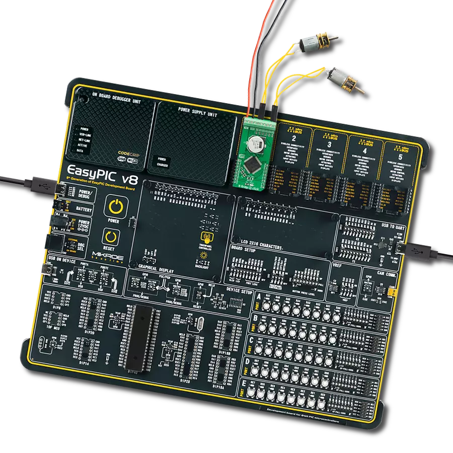
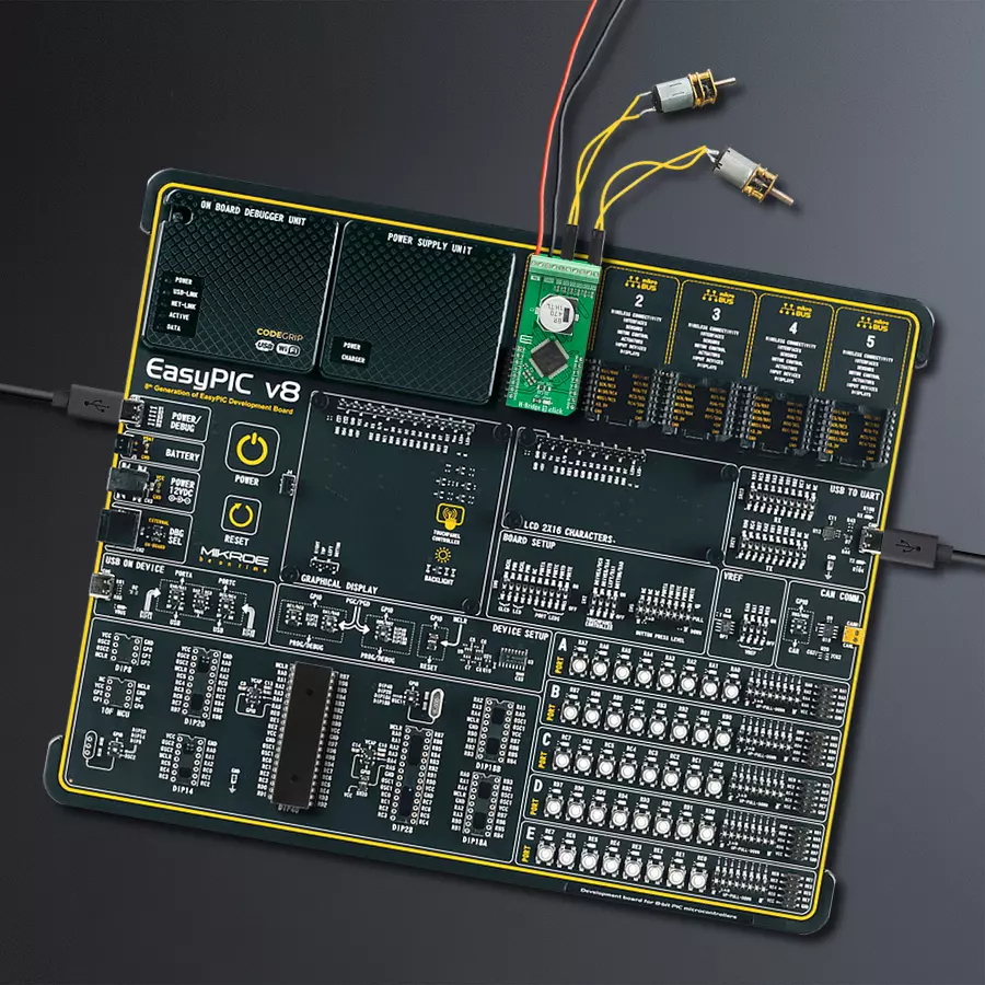
EasyPIC v8 is a development board specially designed for the needs of rapid development of embedded applications. It supports many high pin count 8-bit PIC microcontrollers from Microchip, regardless of their number of pins, and a broad set of unique functions, such as the first-ever embedded debugger/programmer. The development board is well organized and designed so that the end-user has all the necessary elements, such as switches, buttons, indicators, connectors, and others, in one place. Thanks to innovative manufacturing technology, EasyPIC v8 provides a fluid and immersive working experience, allowing access anywhere and under any
circumstances at any time. Each part of the EasyPIC v8 development board contains the components necessary for the most efficient operation of the same board. In addition to the advanced integrated CODEGRIP programmer/debugger module, which offers many valuable programming/debugging options and seamless integration with the Mikroe software environment, the board also includes a clean and regulated power supply module for the development board. It can use a wide range of external power sources, including a battery, an external 12V power supply, and a power source via the USB Type-C (USB-C) connector.
Communication options such as USB-UART, USB DEVICE, and CAN are also included, including the well-established mikroBUS™ standard, two display options (graphical and character-based LCD), and several different DIP sockets. These sockets cover a wide range of 8-bit PIC MCUs, from the smallest PIC MCU devices with only eight up to forty pins. EasyPIC v8 is an integral part of the Mikroe ecosystem for rapid development. Natively supported by Mikroe software tools, it covers many aspects of prototyping and development thanks to a considerable number of different Click boards™ (over a thousand boards), the number of which is growing every day.

Microcontroller Overview
MCU Card / MCU
Architecture
PIC
MCU Memory (KB)
128
Silicon Vendor
Microchip
Pin count
40
RAM (Bytes)
8192
You complete me!
Accessories
DC Gear Motor - 430RPM (3-6V) represents an all-in-one combination of a motor and gearbox, where the addition of gear leads to a reduction of motor speed while increasing the torque output. This gear motor has a spur gearbox, making it a highly reliable solution for applications with lower torque and speed requirements. The most critical parameters for gear motors are speed, torque, and efficiency, which are, in this case, 520RPM with no load and 430RPM at maximum efficiency, alongside a current of 60mA and a torque of 50g.cm. Rated for a 3-6V operational voltage range and clockwise/counterclockwise rotation direction, this motor represents an excellent solution for many functions initially performed by brushed DC motors in robotics, medical equipment, electric door locks, and much more.

Used MCU Pins
mikroBUS™ mapper
Take a closer look
Click board™ Schematic

Step by step
Project assembly

Start by selecting your development board and Click board™. Begin with the EasyPIC v8 as your development board.


Software Support
Library Description
This library contains API for H-Bridge 9 Click driver.
Key functions:
hbridge9_write_register- This function writes a desired data to the selected registerhbridge9_read_register- This function reads a desired data from the selected registerhbridge9_send_actuation_pulse- This function sends an actuation pulse by toggling the ENO pin
Open Source
Code example
The complete application code and a ready-to-use project are available through the NECTO Studio Package Manager for direct installation in the NECTO Studio. The application code can also be found on the MIKROE GitHub account.
/*!
 * @file main.c
 * @brief HBridge9 Click example
 *
 * # Description
 * This example demonstrates the use of H-Bridge 9 Click board.
 *
 * The demo application is composed of two sections :
 *
 * ## Application Init
 * Initializes the driver and performs the Click default configuration which will
 * set the OUT1 to LOW, OUT2 to HIGH polarity, and the runtime to 1000ms.
 *
 * ## Application Task
 * Sends an actuation pulse every 5 seconds which will run the motor for a certain amount of time
 * as set by default configuration.
 *
 * @note
 * The Voltage should be supplied with 6 to 18V power supply.
 * Make sure to use a motor that operates in the above voltage range.
 *
 * @author Stefan Filipovic
 *
 */

#include "board.h"
#include "log.h"
#include "hbridge9.h"

static hbridge9_t hbridge9;
static log_t logger;

void application_init ( void )
{
    log_cfg_t log_cfg;            /**< Logger config object. */
    hbridge9_cfg_t hbridge9_cfg;  /**< Click config object. */

    /**
     * Logger initialization.
     * Default baud rate: 115200
     * Default log level: LOG_LEVEL_DEBUG
     * @note If USB_UART_RX and USB_UART_TX
     * are defined as HAL_PIN_NC, you will
     * need to define them manually for log to work.
     * See @b LOG_MAP_USB_UART macro definition for detailed explanation.
     */
    LOG_MAP_USB_UART( log_cfg );
    log_init( &logger, &log_cfg );
    log_info( &logger, " Application Init " );

    // Click initialization.

    hbridge9_cfg_setup( &hbridge9_cfg );
    HBRIDGE9_MAP_MIKROBUS( hbridge9_cfg, MIKROBUS_1 );
    err_t init_flag = hbridge9_init( &hbridge9, &hbridge9_cfg );
    if ( SPI_MASTER_ERROR == init_flag )
    {
        log_error( &logger, " Application Init Error. " );
        log_info( &logger, " Please, run program again... " );

        for ( ; ; );
    }

    init_flag = hbridge9_default_cfg ( &hbridge9 );
    if ( HBRIDGE9_ERROR == init_flag )
    {
        log_error( &logger, " Default Config Error. " );
        log_info( &logger, " Please, run program again... " );

        for ( ; ; );
    }
    log_info( &logger, " Application Task " );
}

void application_task ( void )
{
    hbridge9_send_actuation_pulse( &hbridge9 );
    log_printf( &logger, " Actuation pulse has been sent. \r\n\n" );
    Delay_ms ( 1000 );
    Delay_ms ( 1000 );
    Delay_ms ( 1000 );
    Delay_ms ( 1000 );
    Delay_ms ( 1000 );
}

int main ( void )
{
    /* Do not remove this line or clock might not be set correctly. */
    #ifdef PREINIT_SUPPORTED
    preinit();
    #endif

    application_init( );

    for ( ; ; )
    {
        application_task( );
    }

    return 0;
}

// ------------------------------------------------------------------------ END


