Create various touchpad adventures with MTCH6102 and PIC18LF45K40
Spark innovation at your fingertips

Published Aug 06, 2023
Click board™
Touchpad Click
Dev. board
EasyPIC v8
Compiler
NECTO Studio
MCU
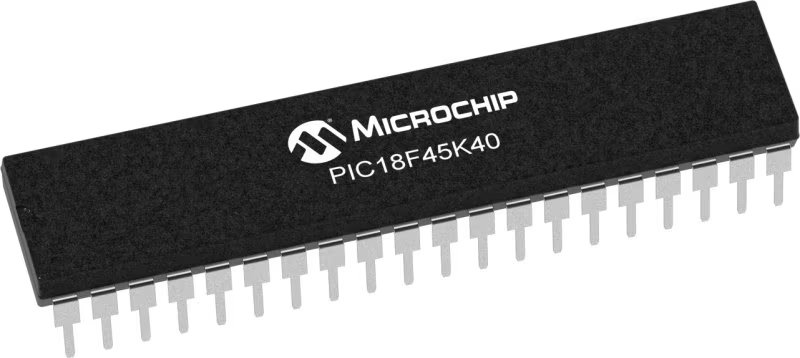
PIC18LF45K40
Incorporate capacitive touch sensing functions into your solution and set new standards
A
A
Hardware Overview
How does it work?
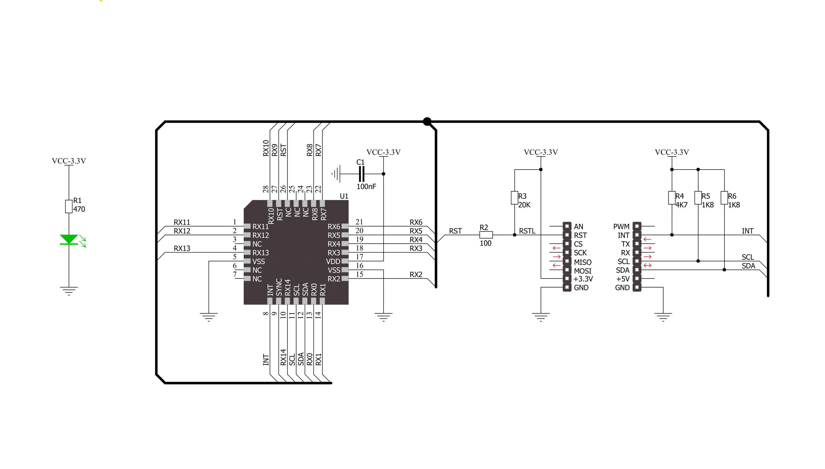
Touchpad Click is based on the MTCH6102, a projected capacitive touch controller from Microchip. This controller utilizes up to fifteen I2C-controllable channels, offering a flexible touch-sensing solution for industry-leading applications such as remote controls, gaming devices, and trackpads. The MTCH6102 controller is very flexible, providing numerous gesture detection patterns such as single click, click and hold, double click, right/left/up/down swipe, and all with a hold function, all in one solution. A clearly defined field on the board's front side represents a touchpad area covered with a sheet of black plastic to
demonstrate the chip's support for cover layers (up to 3mm for plastic and 5mm for glass). This area is a matrix of conductive electrodes on the PCB, electrically isolated from each other, arranged as rows and columns of X and Y in a dimension of 25x17mm. An electrode consists of multiple diamond-shaped elements connected to the next with a conductive neck. Touchpad Click communicates with MCU using the standard I2C 2-Wire interface with a maximum clock frequency of 400kHz, fully adjustable through software registers. An additional ready signal, routed on the INT pin of the mikroBUS™ socket, is added,
indicating when the communication window is available with new data. Besides this pin, this Click board™ has a Reset feature routed to the RST pin on the mikroBUS™ socket, which, with a low logic level, puts the controller into a Reset state. This Click board™ can be operated only with a 3.3V logic voltage level. The board must perform appropriate logic voltage level conversion before using MCUs with different logic levels. Also, this Click board™ comes equipped with a library containing easy-to-use functions and an example code that can be used for further development.

Features overview
Development board
EasyPIC v8 is a development board specially designed for the needs of rapid development of embedded applications. It supports many high pin count 8-bit PIC microcontrollers from Microchip, regardless of their number of pins, and a broad set of unique functions, such as the first-ever embedded debugger/programmer. The development board is well organized and designed so that the end-user has all the necessary elements, such as switches, buttons, indicators, connectors, and others, in one place. Thanks to innovative manufacturing technology, EasyPIC v8 provides a fluid and immersive working experience, allowing access anywhere and under any
circumstances at any time. Each part of the EasyPIC v8 development board contains the components necessary for the most efficient operation of the same board. In addition to the advanced integrated CODEGRIP programmer/debugger module, which offers many valuable programming/debugging options and seamless integration with the Mikroe software environment, the board also includes a clean and regulated power supply module for the development board. It can use a wide range of external power sources, including a battery, an external 12V power supply, and a power source via the USB Type-C (USB-C) connector.
Communication options such as USB-UART, USB DEVICE, and CAN are also included, including the well-established mikroBUS™ standard, two display options (graphical and character-based LCD), and several different DIP sockets. These sockets cover a wide range of 8-bit PIC MCUs, from the smallest PIC MCU devices with only eight up to forty pins. EasyPIC v8 is an integral part of the Mikroe ecosystem for rapid development. Natively supported by Mikroe software tools, it covers many aspects of prototyping and development thanks to a considerable number of different Click boards™ (over a thousand boards), the number of which is growing every day.

Microcontroller Overview
MCU Card / MCU
Architecture
PIC
MCU Memory (KB)
32
Silicon Vendor
Microchip
Pin count
40
RAM (Bytes)
2048
Used MCU Pins
mikroBUS™ mapper
Take a closer look
Click board™ Schematic
Step by step
Project assembly

Start by selecting your development board and Click board™. Begin with the EasyPIC v8 as your development board.


Software Support
Library Description
This library contains API for Touchpad Click driver.
Key functions:
touchpad_get_touch_coordinate- Get touch coordinatetouchpad_get_event_state- Get event statetouchpad_get_gesture_type- Gesture type
Open Source
Code example
The complete application code and a ready-to-use project are available through the NECTO Studio Package Manager for direct installation in the NECTO Studio. The application code can also be found on the MIKROE GitHub account.
/*!
 * \file
 * \brief Touchpad Click example
 *
 * # Description
 * Demo application shows reading of current event:
 *   - touch event (Touch Coordinates)
 *   - Gesture event (gesture type)
 *
 * The demo application is composed of two sections :
 *
 * ## Application Init
 * Configuring Clicks and log objects.
 * Setting the Click in the default configuration.
 *
 * ## Application Task
 * Reads every touch and gesture and this data logs to USBUART.
 *
 * \author Katarina Perendic
 *
 */
// ------------------------------------------------------------------- INCLUDES

#include "board.h"
#include "log.h"
#include "touchpad.h"

// ------------------------------------------------------------------ VARIABLES

static touchpad_t touchpad;
static log_t logger;

// ------------------------------------------------------ APPLICATION FUNCTIONS

void application_init ( void )
{
    log_cfg_t log_cfg;
    touchpad_cfg_t cfg;

    /**
     * Logger initialization.
     * Default baud rate: 115200
     * Default log level: LOG_LEVEL_DEBUG
     * @note If USB_UART_RX and USB_UART_TX
     * are defined as HAL_PIN_NC, you will
     * need to define them manually for log to work.
     * See @b LOG_MAP_USB_UART macro definition for detailed explanation.
     */
    LOG_MAP_USB_UART( log_cfg );
    log_init( &logger, &log_cfg );
    log_info( &logger, "---- Application Init ----" );

    //  Click initialization.

    touchpad_cfg_setup( &cfg );
    TOUCHPAD_MAP_MIKROBUS( cfg, MIKROBUS_1 );
    touchpad_init( &touchpad, &cfg );

    touchpad_default_cfg( &touchpad );

    log_info( &logger, "---- Waiting for a new touch or gesure event ----" );
    Delay_ms ( 500 );
}

void application_task ( void )
{
    uint8_t state;
    uint8_t gesture;
    touchpad_cord_t cord;

    //  Task implementation.

    Delay_ms ( 50 );
    state = touchpad_get_event_state( &touchpad );
    if ( state == TOUCHPAD_EVENT_TOUCH )
    {
        touchpad_get_touch_coordinate( &touchpad, &cord );

        log_printf( &logger, "\r\n>> Touch coordinate <<" );
        log_printf( &logger, "\r\n>> ........... <<\r\n" );
        log_printf( &logger, "** X cord: %d \r\n** Y cord: %d \r\n", cord.x, cord.y );
        log_printf( &logger, ">> ........... <<\r\n" );
        Delay_ms ( 50 );
    }
    else if ( state == TOUCHPAD_EVENT_GESTURE )
    {
        gesture = touchpad_get_gesture_type( &touchpad );
        switch( gesture )
        {
            case TOUCHPAD_GS_CLICK_AND_HOLD :
            {
                log_printf( &logger, "**Gesture type: Click and Hold\r\n" );
                break;
            }
            case TOUCHPAD_GS_DOUBLE_CLICK :
            {
                log_printf( &logger, "\r\n**Gesture type: Double Click\r\n" );
                break;
            }
            case TOUCHPAD_GS_SINGLE_CLICK :
            {
                log_printf( &logger, "\r\n**Gesture type: Single Click\r\n" );
                break;
            }
            case TOUCHPAD_GS_DOWN_SWIPE :
            {
                log_printf( &logger, "\r\n**Gesture type: Down Swipe\r\n" );
                break;
            }
            case TOUCHPAD_GS_DOWN_SWIPE_AND_HOLD :
            {
                log_printf( &logger, "\r\n**Gesture type: Down Swipe and Hold\r\n" );
                break;
            }
            case TOUCHPAD_GS_RIGHT_SWIPE :
            {
                log_printf( &logger, "\r\n**Gesture type: Right Swipe\r\n" );
                break;
            }
            case TOUCHPAD_GS_RIGHT_SWIPE_AND_HOLD :
            {
                log_printf( &logger, "\r\n**Gesture type: Right Swipe and Hold\r\n" );
                break;
            }
            case TOUCHPAD_GS_UP_SWIPE :
            {
                log_printf( &logger, "\r\n**Gesture type: Up Swipe\r\n" );
                break;
            }
            case TOUCHPAD_GS_UP_SWIPE_AND_HOLD :
            {
                log_printf( &logger, "\r\n**Gesture type: Up Swipe and Hold\r\n" );
                break;
            }
            case TOUCHPAD_GS_LEFT_SWIPE :
            {
                log_printf( &logger, "\r\n**Gesture type: Left Swipe\r\n" );
                break;
            }
            case TOUCHPAD_GS_LEFT_SWIPE_AND_HOLD :
            {
                log_printf( &logger, "\r\n**Gesture type: Left Swipe and Hold\r\n" );
                break;
            }
       }
    }
}

int main ( void )
{
    /* Do not remove this line or clock might not be set correctly. */
    #ifdef PREINIT_SUPPORTED
    preinit();
    #endif

    application_init( );

    for ( ; ; )
    {
        application_task( );
    }

    return 0;
}


// ------------------------------------------------------------------------ END


