Bring the unseen world of magnetic fields to life with LIS2MDL and PIC18F24K50
3D magnetic insights available now!

Published Nov 01, 2023
Click board™
3D Hall 3 Click
Dev. board
EasyPIC v8
Compiler
NECTO Studio
MCU
PIC18F24K50
Learn how our solution future-proofs your projects by providing comprehensive magnetic field data along three axes, ensuring accuracy and adaptability in an ever-changing world
A
A
Hardware Overview
How does it work?
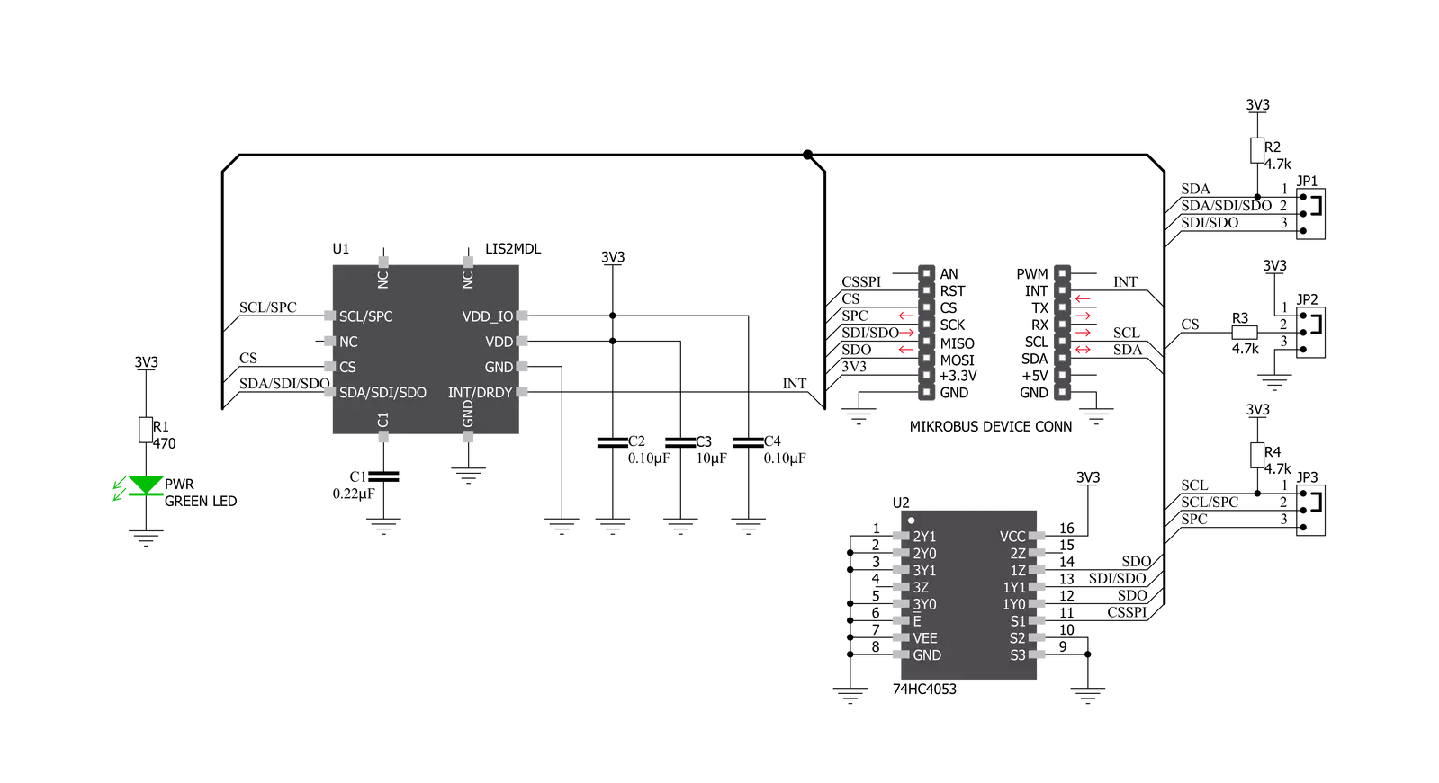
3D Hall 3 Click is based on the LIS2MDL, a low power 3D magnetic sensor, from STMicroelectronics. This sensor relies on a Hall effect to accurately sense magnetic field changes on three perpendicular axes. The internal magnetic field sensing elements are multiplexed and connected to a 16bit low noise Analog to Digital Converter (ADC), which sequentially samples each sensor, providing 16-bit spatial data over the digital interface. An additional thermal sensor is also available, and it is used for thermal compensation. The magnetic sensor has a very low pin count. Therefore, SPI and I2C lines are multiplexed on the same pins. In addition, the SPI data in (SDI) and SPI data out (SDO) share the same pin. In order to allow functionality for both SPI READ and SPI WRITE functions, 3D Hall 3 click incorporates another IC: the 74HC4053, a triple 2-channel multiplexer/demultiplexer IC from NXP is used in conjunction with the RST pin of the mikroBUS™, labeled as CSS. This allows to demultiplex the SDI/SDO pin of the LIS2MDL and route the two resulting pins to appropriate pins of the mikroBUS™ (SDI and SDO). The rest of the communication interface selection procedure relies on switching the appropriate SMD jumpers, grouped under the I2C/SPI label. Note that all the I2C/SPI group jumpers need to be switched at the same side: all three should either be soldered as I2C or SPI. If one of them shows in the opposite position from the rest, the communication with the IC might not be possible. The power consumption is a big concern as of lately, with the
introduction of the IoT. The ability to work in a low power mode is a must for every device which is to be used for any type of IoT networking. The LIS2MDL magnetic sensor features two operational modes, with the addition of a low-pass filter (LPF). The power consumption is in a close relationship with the data output refresh rate (ODR). When operated in Low Power mode, and with the LPF and the offset cancelation turned OFF, the power consumption of the sensor alone drops down to 25 μA. Turning on the LPF and the offset cancelation will double the power consumption for the same ODR frequency to 50 μA, which is still in a domain of micropower consumption. However, filtering and offset cancelation options offer less noise and more accurate readings for both high-resolution and low-resolution modes. The LIS2MDL magnetic sensor also features a powerful programmable interrupt engine, which allows many event sources to be signaled via the interrupt pin (INT/DRDY), which is routed from the sensor to the mikroBUS™ INT pin. A very useful function of the interrupt engine is the signaling of the data ready event. That way, the host MCU does not have to poll the sensor for the data acquisition. The sensor can simply trigger an interrupt when the data is ready for reading. The interrupt engine allows some other customizations of the interrupt signal, such as the polarity, pulse/latch mode, and so on. The sensor provides raw data output, based on a strength of the magnetic field. The measurement is affected by many factors: slight manufacturing
differences between ICs affect the readings, even the slight differences between Hall plates within the same IC might affect the accuracy, although the IC contains highly matched sensing elements. Also, the altitude might affect the readings, as well as temperature changes. Therefore, the sensor IC is equipped with the thermal sensor, used to measure the influence of the ambient temperature. Unlike errors which occur due to the influence of other parameters, the influence of the temperature is not linear, so a proper firmware development approach by using LUT tables is highly advisable. The power mode, output data rate, interrupt thresholds for each axis, and other working parameters, including the availability of the I2C interface, are contained within the configuration registers of the LIS2MDL magnetic sensor. The sensor is highly configurable, with many configuration options. The LIS2MDL datasheet contains an in-depth explanation of all the registers and their functionality. However, 3D Hall 3 software library contains simplified functions that allow straight-forward readings to be performed, reducing the steps needed for a proper initialization and configuration of the device. This Click board™ can be operated only with a 3.3V logic voltage level. The board must perform appropriate logic voltage level conversion before using MCUs with different logic levels. Also, it comes equipped with a library containing functions and an example code that can be used as a reference for further development.


Features overview
Development board
EasyPIC v8 is a development board specially designed for the needs of rapid development of embedded applications. It supports many high pin count 8-bit PIC microcontrollers from Microchip, regardless of their number of pins, and a broad set of unique functions, such as the first-ever embedded debugger/programmer. The development board is well organized and designed so that the end-user has all the necessary elements, such as switches, buttons, indicators, connectors, and others, in one place. Thanks to innovative manufacturing technology, EasyPIC v8 provides a fluid and immersive working experience, allowing access anywhere and under any
circumstances at any time. Each part of the EasyPIC v8 development board contains the components necessary for the most efficient operation of the same board. In addition to the advanced integrated CODEGRIP programmer/debugger module, which offers many valuable programming/debugging options and seamless integration with the Mikroe software environment, the board also includes a clean and regulated power supply module for the development board. It can use a wide range of external power sources, including a battery, an external 12V power supply, and a power source via the USB Type-C (USB-C) connector.
Communication options such as USB-UART, USB DEVICE, and CAN are also included, including the well-established mikroBUS™ standard, two display options (graphical and character-based LCD), and several different DIP sockets. These sockets cover a wide range of 8-bit PIC MCUs, from the smallest PIC MCU devices with only eight up to forty pins. EasyPIC v8 is an integral part of the Mikroe ecosystem for rapid development. Natively supported by Mikroe software tools, it covers many aspects of prototyping and development thanks to a considerable number of different Click boards™ (over a thousand boards), the number of which is growing every day.

Microcontroller Overview
MCU Card / MCU
Architecture
PIC
MCU Memory (KB)
16
Silicon Vendor
Microchip
Pin count
28
RAM (Bytes)
2048
Used MCU Pins
mikroBUS™ mapper
Take a closer look
Click board™ Schematic
Step by step
Project assembly

Start by selecting your development board and Click board™. Begin with the EasyPIC v8 as your development board.


Software Support
Library Description
This library contains API for 3D Hall 3 Click driver.
Key functions:
c3dhall3_read_xyz- This function reads xyz values from the modulec3dhall3_write_offset- This function writes offest values to the modulec3dhall3_interrupt_threshold- This function sets desired threshold value.
Open Source
Code example
The complete application code and a ready-to-use project are available through the NECTO Studio Package Manager for direct installation in the NECTO Studio. The application code can also be found on the MIKROE GitHub account.
/*!
 * \file
 * \brief 3DHall3 Click example
 *
 * # Description
 * This example returns values of X,Y and Z axes.
 *
 * The demo application is composed of two sections :
 *
 * ## Application Init
 * Initializes driver and sets basic configuration.
 *
 * ## Application Task
 * Reads the values of the X,Y and Z axes.
 *
 *
 * \author Petar Suknjaja
 *
 */
// ------------------------------------------------------------------- INCLUDES

#include "board.h"
#include "log.h"
#include "c3dhall3.h"

// ------------------------------------------------------------------ VARIABLES

static c3dhall3_t c3dhall3;
static log_t logger;

// ------------------------------------------------------ APPLICATION FUNCTIONS

void application_init ( void )
{
    log_cfg_t log_cfg;
    c3dhall3_cfg_t cfg;

    /**
     * Logger initialization.
     * Default baud rate: 115200
     * Default log level: LOG_LEVEL_DEBUG
     * @note If USB_UART_RX and USB_UART_TX
     * are defined as HAL_PIN_NC, you will
     * need to define them manually for log to work.
     * See @b LOG_MAP_USB_UART macro definition for detailed explanation.
     */
    LOG_MAP_USB_UART( log_cfg );
    log_init( &logger, &log_cfg );
    log_info( &logger, "---- Application Init ----" );

    //  Click initialization.

    c3dhall3_cfg_setup( &cfg );
    C3DHALL3_MAP_MIKROBUS( cfg, MIKROBUS_1 );
    c3dhall3_init( &c3dhall3, &cfg );
    c3dhall3_default_cfg ( &c3dhall3 );
    log_info( &logger, "---- System Init ----" );
}

void application_task ( void )
{
    int16_t axes_xyz[ 3 ];

    c3dhall3_read_xyz( &c3dhall3, axes_xyz );
    log_printf( &logger, "X: %d \r\n", axes_xyz[ 0 ] );
    log_printf( &logger, "Y: %d \r\n", axes_xyz[ 1 ] );
    log_printf( &logger, "Z: %d \r\n", axes_xyz[ 2 ] );

    Delay_ms ( 500 );
}

int main ( void )
{
    /* Do not remove this line or clock might not be set correctly. */
    #ifdef PREINIT_SUPPORTED
    preinit();
    #endif

    application_init( );

    for ( ; ; )
    {
        application_task( );
    }

    return 0;
}

// ------------------------------------------------------------------------ END


