Achieve unparalleled accuracy in current measurement with MAX40080 and PIC18F2455
Unlock new possibilities with current sensing
Published Nov 01, 2023
Click board™
Current 6 Click
Dev. board
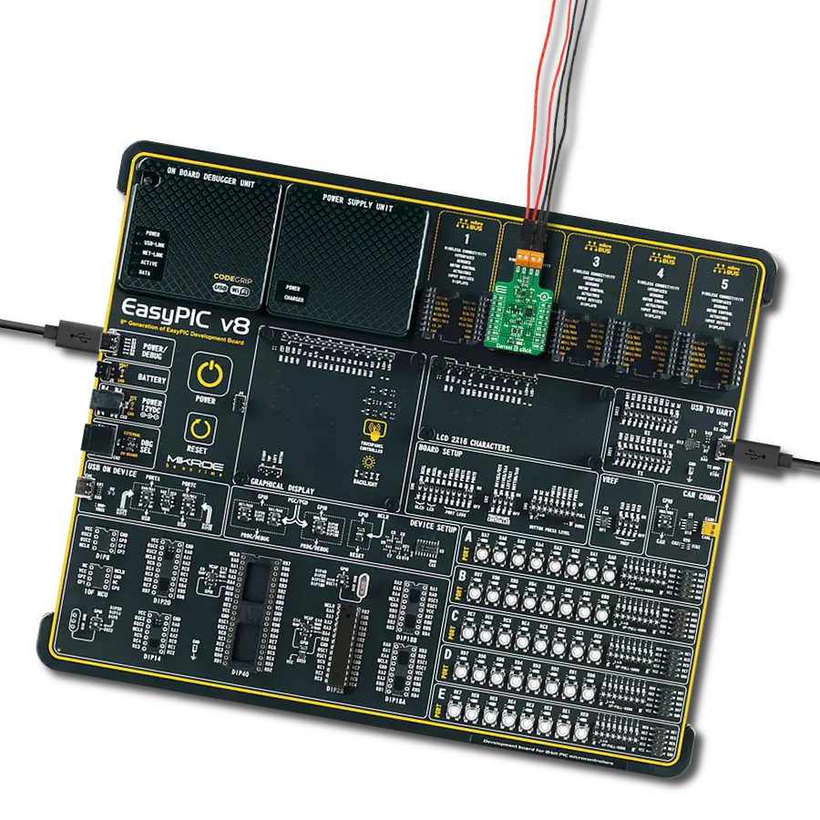
EasyPIC v8
Compiler
NECTO Studio
MCU
PIC18F2455
Effortlessly manage dynamic loads with our current sensing technology, seamlessly adapting to current demand changes
A
A
Hardware Overview
How does it work?
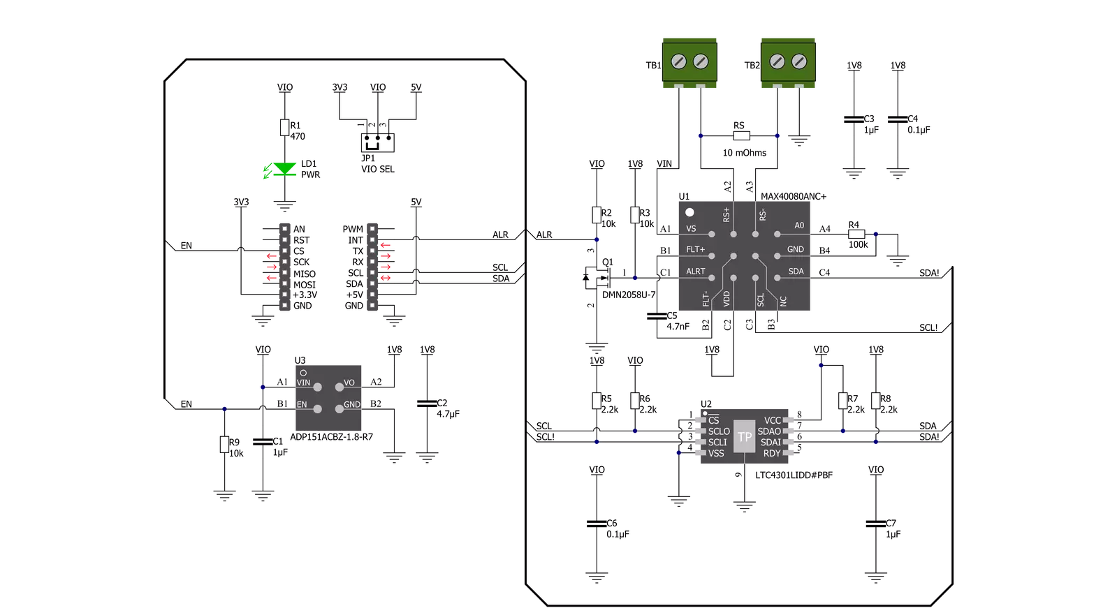
Current 6 Click is based on the MAX40080, a high-precision, fast sample-rate digital current-sense amplifier from Analog Devices. The MAX40080 measures current and common-mode voltage ranging from -0.1V to 36V and converts the data into digital form through an I2C-compatible two-wire serial interface allowing access to conversion results. Also, setting the input voltage sense using the I2C register, ±50mV or ±10mV, will allow one to select two measuring ranges from 0A to 1A or 0A to 5A. This Click board™ communicates with MCU using the standard I2C 2-Wire interface for configuring and checking the device's status. Standard I2C commands allow reading the data and configuring other operating characteristics. While reading the current/voltage registers, any measured current and voltage changes are ignored until the read is completed. The current/voltage register is updated for the new measurement upon
completion of the read operation. The MAX40080 has a unique I2C slave address selection method based on a single R4 resistor. By selecting the resistors of precisely defined resistances from Table 1, it is possible to choose 32 different slave addresses corresponding to 32 different resistor values in the attached datasheet. The default value of the R4 resistor is 100kΩ which corresponds to an address of 0x01. In addition, it also features a wake-up current threshold and auto-shutdown mode when the I2C interface is inactive, both designed to minimize power consumption. Since the sensor for operation requires a 1.8V logic voltage level to work correctly, a small regulating LDO is used, the ADP151 from Analog Devices, providing a 1.8V out of mikroBUS™ rails. This LDO uses the Enable pin labeled as EN and routed to the CS pin of the mikroBUS™ socket to optimize power consumption, used for its power ON/OFF
purposes. That's why the LTC4301L voltage-level translator is also featured. The I2C interface bus lines are routed to the voltage-level translator, allowing this Click board™ to work properly with both 3.3V and 5V MCUs. It also possesses an additional interrupt signal, routed on the INT pin of the mikroBUS™ socket labeled as INT, indicating when a specific interrupt event occurs, such as overcurrent/voltage, under voltage, FIFO full/overflow, a wake-up current threshold reached, and more. This Click board™ can operate with either 3.3V or 5V logic voltage levels selected via the VIO SEL jumper. This way, both 3.3V and 5V capable MCUs can use the communication lines properly. Also, this Click board™ comes equipped with a library containing easy-to-use functions and an example code that can be used, as a reference, for further development.


Features overview
Development board
EasyPIC v8 is a development board specially designed for the needs of rapid development of embedded applications. It supports many high pin count 8-bit PIC microcontrollers from Microchip, regardless of their number of pins, and a broad set of unique functions, such as the first-ever embedded debugger/programmer. The development board is well organized and designed so that the end-user has all the necessary elements, such as switches, buttons, indicators, connectors, and others, in one place. Thanks to innovative manufacturing technology, EasyPIC v8 provides a fluid and immersive working experience, allowing access anywhere and under any
circumstances at any time. Each part of the EasyPIC v8 development board contains the components necessary for the most efficient operation of the same board. In addition to the advanced integrated CODEGRIP programmer/debugger module, which offers many valuable programming/debugging options and seamless integration with the Mikroe software environment, the board also includes a clean and regulated power supply module for the development board. It can use a wide range of external power sources, including a battery, an external 12V power supply, and a power source via the USB Type-C (USB-C) connector.
Communication options such as USB-UART, USB DEVICE, and CAN are also included, including the well-established mikroBUS™ standard, two display options (graphical and character-based LCD), and several different DIP sockets. These sockets cover a wide range of 8-bit PIC MCUs, from the smallest PIC MCU devices with only eight up to forty pins. EasyPIC v8 is an integral part of the Mikroe ecosystem for rapid development. Natively supported by Mikroe software tools, it covers many aspects of prototyping and development thanks to a considerable number of different Click boards™ (over a thousand boards), the number of which is growing every day.

Microcontroller Overview
MCU Card / MCU

Architecture
PIC
MCU Memory (KB)
24
Silicon Vendor
Microchip
Pin count
28
RAM (Bytes)
2048
Used MCU Pins
mikroBUS™ mapper
Take a closer look
Click board™ Schematic
Step by step
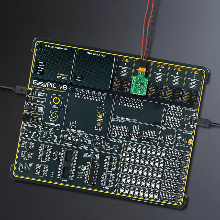
Project assembly

Start by selecting your development board and Click board™. Begin with the EasyPIC v8 as your development board.


Track your results in real time
Application Output
1. Application Output - In Debug mode, the 'Application Output' window enables real-time data monitoring, offering direct insight into execution results. Ensure proper data display by configuring the environment correctly using the provided tutorial.

2. UART Terminal - Use the UART Terminal to monitor data transmission via a USB to UART converter, allowing direct communication between the Click board™ and your development system. Configure the baud rate and other serial settings according to your project's requirements to ensure proper functionality. For step-by-step setup instructions, refer to the provided tutorial.

3. Plot Output - The Plot feature offers a powerful way to visualize real-time sensor data, enabling trend analysis, debugging, and comparison of multiple data points. To set it up correctly, follow the provided tutorial, which includes a step-by-step example of using the Plot feature to display Click board™ readings. To use the Plot feature in your code, use the function: plot(*insert_graph_name*, variable_name);. This is a general format, and it is up to the user to replace 'insert_graph_name' with the actual graph name and 'variable_name' with the parameter to be displayed.

Software Support
Library Description
This library contains API for Current 6 Click driver.
Key functions:
current6_get_alert_pin- This function returns the alert pin logic statecurrent6_read_data- This function reads the input voltage and current measurement valuescurrent6_get_status- This function reads and clears the status register
Open Source
Code example
The complete application code and a ready-to-use project are available through the NECTO Studio Package Manager for direct installation in the NECTO Studio. The application code can also be found on the MIKROE GitHub account.
/*!
* @file main.c
* @brief Current6 Click example
*
* # Description
* This example demonstrates the use of Current 6 Click board by reading
* the input voltage and current measurements.
*
* The demo application is composed of two sections :
*
* ## Application Init
* Initializes the driver and performs the Click default configuration.
*
* ## Application Task
* Waits for the FIFO data interrupt and then reads the measurements of
* the input voltage and current and displays the results on the USB UART
* approximately once per second.
*
* @author Stefan Filipovic
*
*/
#include "board.h"
#include "log.h"
#include "current6.h"
static current6_t current6;
static log_t logger;
void application_init ( void )
{
log_cfg_t log_cfg; /**< Logger config object. */
current6_cfg_t current6_cfg; /**< Click config object. */
/**
* Logger initialization.
* Default baud rate: 115200
* Default log level: LOG_LEVEL_DEBUG
* @note If USB_UART_RX and USB_UART_TX
* are defined as HAL_PIN_NC, you will
* need to define them manually for log to work.
* See @b LOG_MAP_USB_UART macro definition for detailed explanation.
*/
LOG_MAP_USB_UART( log_cfg );
log_init( &logger, &log_cfg );
log_info( &logger, " Application Init " );
// Click initialization.
current6_cfg_setup( ¤t6_cfg );
CURRENT6_MAP_MIKROBUS( current6_cfg, MIKROBUS_1 );
if ( I2C_MASTER_ERROR == current6_init( ¤t6, ¤t6_cfg ) )
{
log_error( &logger, " Communication init." );
for ( ; ; );
}
if ( CURRENT6_ERROR == current6_default_cfg ( ¤t6 ) )
{
log_error( &logger, " Default configuration." );
for ( ; ; );
}
log_info( &logger, " Application Task " );
}
void application_task ( void )
{
if ( current6_get_alert_pin ( ¤t6 ) )
{
uint16_t status;
if ( CURRENT6_OK == current6_get_status ( ¤t6, &status ) )
{
if ( status & CURRENT6_FIFO_CFG_DATA_OVERFLOW_MASK )
{
float voltage, current;
if ( CURRENT6_OK == current6_read_data ( ¤t6, &voltage, ¤t ) )
{
log_printf( &logger, " Voltage: %.3f V\r\n Current: %.3f A\r\n\n", voltage, current );
}
}
}
}
}
int main ( void )
{
/* Do not remove this line or clock might not be set correctly. */
#ifdef PREINIT_SUPPORTED
preinit();
#endif
application_init( );
for ( ; ; )
{
application_task( );
}
return 0;
}
// ------------------------------------------------------------------------ END
Additional Support
Resources
Category:Current sensor


