Experience the freedom of accurate angular measurement with AS5247U and PIC18F26K20
Unlocking angular insights: The ultimate solution for 360-degree magnet rotation
Published Nov 01, 2023
Click board™
Magnetic Rotary 6 Click
Dev. board
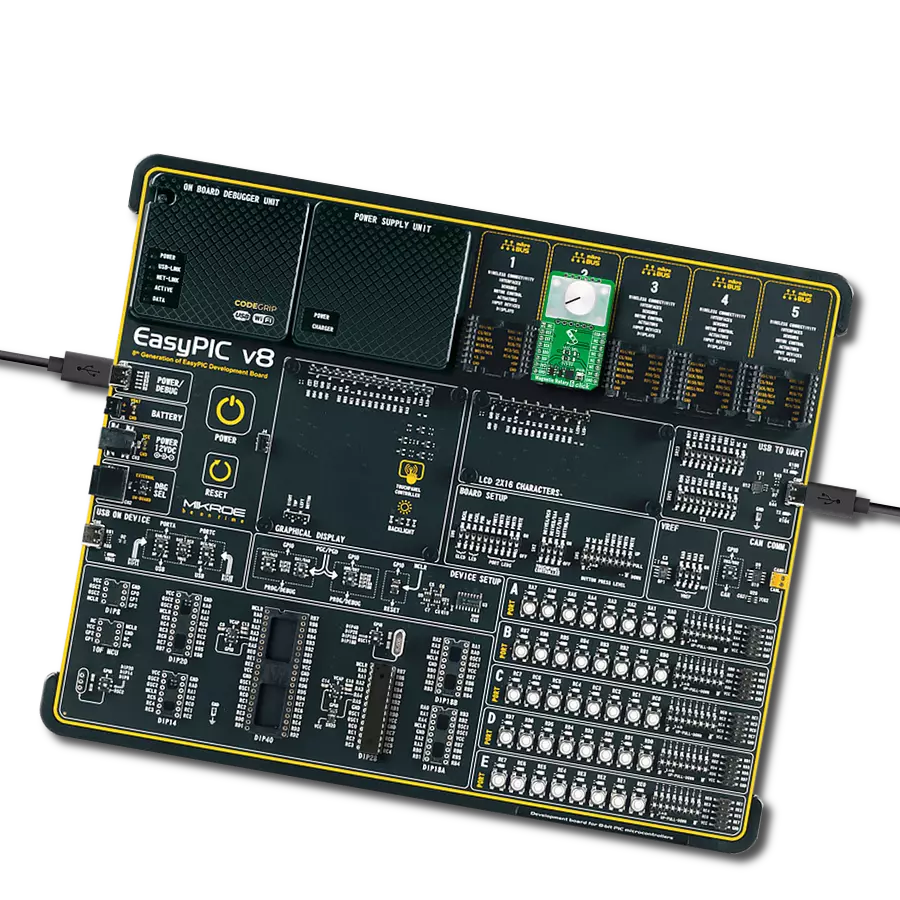
EasyPIC v8
Compiler
NECTO Studio
MCU
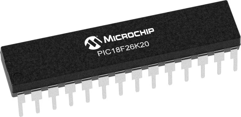
PIC18F26K20
Experience unparalleled accuracy in angular measurement with our innovative sensor, capable of tracking magnet rotation over the entire 360-degree spectrum
A
A
Hardware Overview
How does it work?
Magnetic Rotary 6 Click is based on the AS5247U, a high-resolution dual rotary position sensor for fast absolute angle measurement over a full 360-degree range from ams AG. The core of the AS5247U represents a CMOS technology Hall-effect magnetic sensor that converts the magnetic field component perpendicular to the surface of the chip into a digital value. It supports high-speed applications up to 28krpm and allows a host MCU to read 14-bit absolute angle position data and to program non-volatile settings without a dedicated programmer. The AS5247U is also equipped with a Dynamic Angle Error Compensation block that corrects the calculated angle regarding latency by using a linear prediction calculation algorithm. The AS5247U communicates with the MCU using a standard SPI interface. The signals from its internal Hall sensors are amplified and filtered before their conversion
by the ADC and then processed by the CORDIC block to compute the angle and magnitude of the magnetic field vector. The intensity of the magnetic field is used by the automatic gain control (AGC) to adjust the amplification level to compensate for temperature and magnetic field variations. This Click board™ also comes with onboard headers reserved for incremental and commutation signals of their respective A/B/I and U/V/W signals alongside embedded self-diagnostics. Incremental movements are indicated on a set of ABI signals with a maximum resolution of 16384 steps / 4096 pulses per revolution. The resolution of the ABI signal is programmable for 10 to 14 bits. Brushless DC (BLDC) motors are also controllable through a standard UVW commutation interface with a programmable number of pole pairs from 1 to 7. At constant rotation speed, the latency time is
internally compensated by the AS5247U, reducing the dynamic angle error at the SPI, ABI, and UVW outputs. The AS5047D also allows selection between a UVW output interface and a PWM-encoded interface on the W pin, which can be seen as an absolute angle position. A unique addition to this board is a position for a rotary magnet holder designed to be used alongside a magnetic rotary position sensor, allowing fast prototyping and quick measurements during development. This Click board™ can operate with either 3.3V or 5V logic voltage levels selected via the VCC SEL jumper. This way, both 3.3V and 5V capable MCUs can use the communication lines properly. Also, this Click board™ comes equipped with a library containing easy-to-use functions and an example code that can be used as a reference for further development.


Features overview
Development board
EasyPIC v8 is a development board specially designed for the needs of rapid development of embedded applications. It supports many high pin count 8-bit PIC microcontrollers from Microchip, regardless of their number of pins, and a broad set of unique functions, such as the first-ever embedded debugger/programmer. The development board is well organized and designed so that the end-user has all the necessary elements, such as switches, buttons, indicators, connectors, and others, in one place. Thanks to innovative manufacturing technology, EasyPIC v8 provides a fluid and immersive working experience, allowing access anywhere and under any
circumstances at any time. Each part of the EasyPIC v8 development board contains the components necessary for the most efficient operation of the same board. In addition to the advanced integrated CODEGRIP programmer/debugger module, which offers many valuable programming/debugging options and seamless integration with the Mikroe software environment, the board also includes a clean and regulated power supply module for the development board. It can use a wide range of external power sources, including a battery, an external 12V power supply, and a power source via the USB Type-C (USB-C) connector.
Communication options such as USB-UART, USB DEVICE, and CAN are also included, including the well-established mikroBUS™ standard, two display options (graphical and character-based LCD), and several different DIP sockets. These sockets cover a wide range of 8-bit PIC MCUs, from the smallest PIC MCU devices with only eight up to forty pins. EasyPIC v8 is an integral part of the Mikroe ecosystem for rapid development. Natively supported by Mikroe software tools, it covers many aspects of prototyping and development thanks to a considerable number of different Click boards™ (over a thousand boards), the number of which is growing every day.

Microcontroller Overview
MCU Card / MCU
Architecture
PIC
MCU Memory (KB)
64
Silicon Vendor
Microchip
Pin count
28
RAM (Bytes)
3936
You complete me!
Accessories
Rotary Magnetic Holder is an addition designed for use alongside a magnetic rotary position sensor. It comes with a plastic stand measuring 22x16x10 millimeters (L x W x H), as well as an adjustable shaft with a 6mm diameter magnet. The plastic frame has four round feet that fit into holes in the board near the magnetic rotary position sensor, with a 6mm diameter hole on top to match the adjustable shaft that carries the magnet. This shaft has a height adjustment screw on it, allowing the user to adjust it between 18 and 22 millimeters. This way, fast prototyping and quick measurements of the magnet characteristics are allowed during development.

Used MCU Pins
mikroBUS™ mapper
Take a closer look
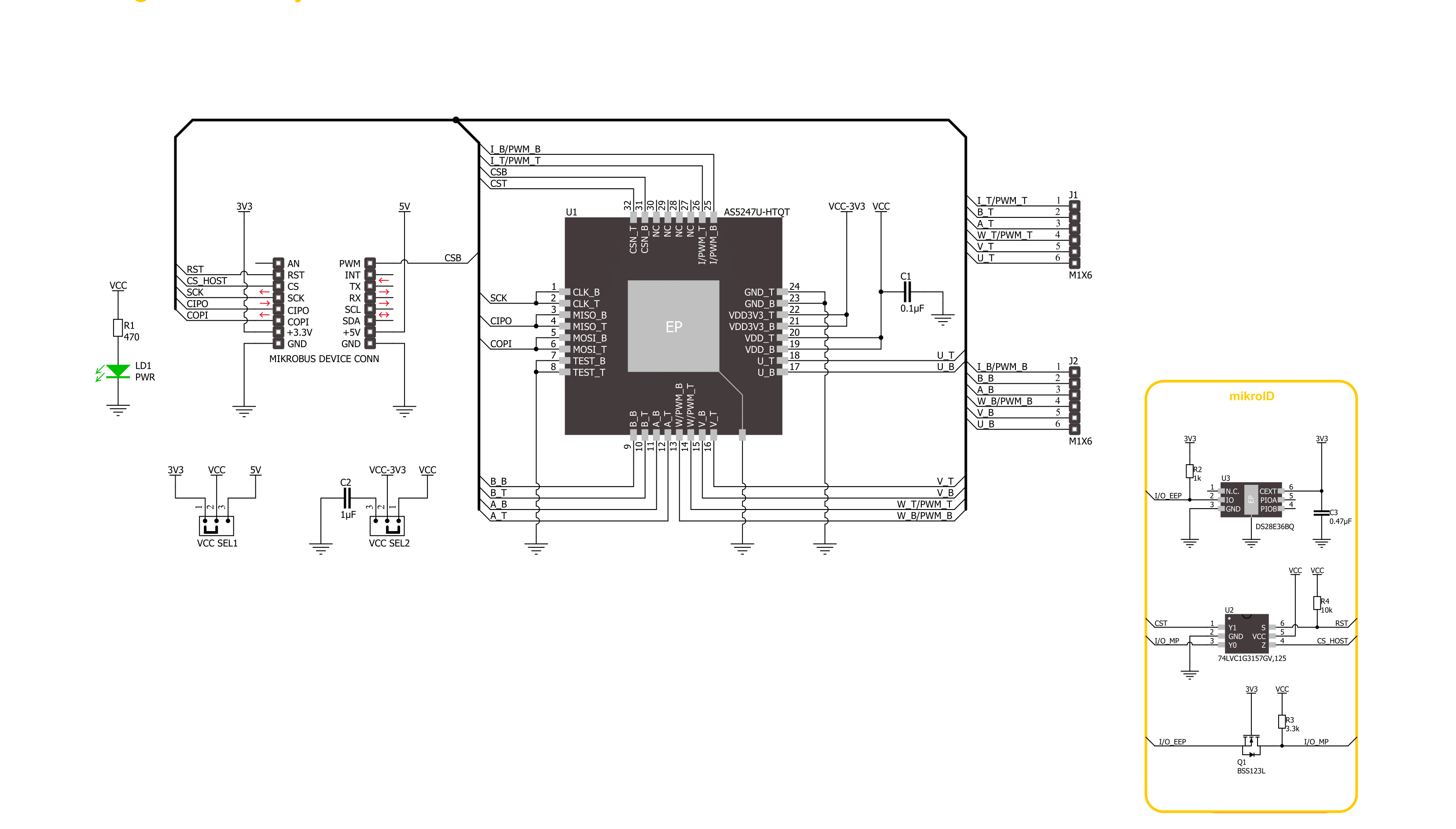
Click board™ Schematic
Step by step
Project assembly

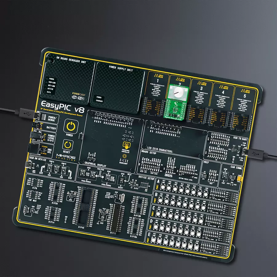
Start by selecting your development board and Click board™. Begin with the EasyPIC v8 as your development board.


Software Support
Library Description
This library contains API for Magnetic Rotary 6 Click driver.
Key functions:
magneticrotary6_write_register- This function writes a desired data to the selected register of a desired sensor die by using SPI serial interfacemagneticrotary6_get_angle- This function reads the absolute position raw data of a desired sensor die and converts it to degrees (Angle)magneticrotary6_set_direction- This function sets the rotation direction of a desired sensor die
Open Source
Code example
The complete application code and a ready-to-use project are available through the NECTO Studio Package Manager for direct installation in the NECTO Studio. The application code can also be found on the MIKROE GitHub account.
/*!
 * @file main.c
 * @brief MagneticRotary6 Click example
 *
 * # Description
 * This example demonstrates the use of Magnetic Rotary 6 Click board by reading and displaying
 * the magnet's angular position in degrees measured by the bottom and top sensor dies.
 *
 * The demo application is composed of two sections :
 *
 * ## Application Init
 * Initializes the driver and performs the Click default configuration which sets the magnet
 * rotation direction for the bottom die to clockwise and for the top die to counter-clockwise.
 *
 * ## Application Task
 * Reads the magnet's angular position from both sensor dies in degrees every 100ms and displays
 * the results on the USB UART.
 *
 * @author Stefan Filipovic
 *
 */

#include "board.h"
#include "log.h"
#include "magneticrotary6.h"

static magneticrotary6_t magneticrotary6;
static log_t logger;

void application_init ( void )
{
    log_cfg_t log_cfg;  /**< Logger config object. */
    magneticrotary6_cfg_t magneticrotary6_cfg;  /**< Click config object. */

    /**
     * Logger initialization.
     * Default baud rate: 115200
     * Default log level: LOG_LEVEL_DEBUG
     * @note If USB_UART_RX and USB_UART_TX
     * are defined as HAL_PIN_NC, you will
     * need to define them manually for log to work.
     * See @b LOG_MAP_USB_UART macro definition for detailed explanation.
     */
    LOG_MAP_USB_UART( log_cfg );
    log_init( &logger, &log_cfg );
    log_info( &logger, " Application Init " );

    // Click initialization.
    magneticrotary6_cfg_setup( &magneticrotary6_cfg );
    MAGNETICROTARY6_MAP_MIKROBUS( magneticrotary6_cfg, MIKROBUS_1 );
    if ( SPI_MASTER_ERROR == magneticrotary6_init( &magneticrotary6, &magneticrotary6_cfg ) )
    {
        log_error( &logger, " Communication init." );
        for ( ; ; );
    }

    if ( MAGNETICROTARY6_ERROR == magneticrotary6_default_cfg ( &magneticrotary6 ) )
    {
        log_error( &logger, " Default configuration." );
        for ( ; ; );
    }

    log_info( &logger, " Application Task " );
}

void application_task ( void )
{
    float angle;
    if ( MAGNETICROTARY6_OK == magneticrotary6_get_angle ( &magneticrotary6, MAGNETICROTARY6_DIE_BOTTOM, &angle ) )
    {
        log_printf( &logger, " Angle (bottom die): %.1f degrees\r\n", angle );
    }
    if ( MAGNETICROTARY6_OK == magneticrotary6_get_angle ( &magneticrotary6, MAGNETICROTARY6_DIE_TOP, &angle ) )
    {
        log_printf( &logger, " Angle (top die): %.1f degrees\r\n\n", angle );
    }
    Delay_ms ( 100 );
}

int main ( void )
{
    /* Do not remove this line or clock might not be set correctly. */
    #ifdef PREINIT_SUPPORTED
    preinit();
    #endif

    application_init( );

    for ( ; ; )
    {
        application_task( );
    }

    return 0;
}

// ------------------------------------------------------------------------ END
Additional Support
Resources
Category:Magnetic


