Ensure optimal performance for your DC motor applications with DRV8823 and STM32F407VGT6
Experience DC motor control like never before with our H-Bridge solution, a powerhouse of innovation.
Published Dec 29, 2023
Click board™
H-Bridge 12 Click
Dev. board
Clicker 4 for STM32F4
Compiler
NECTO Studio
MCU
STM32F407VGT6
Transform your motors into marvels of motion with our innovative H-Bridge solution. Unleash the potential of N-channel power MOSFETs configured in a full-bridge layout, delivering a symphony of power and precision to elevate your motor control experience to unparalleled heights.
A
A
Hardware Overview
How does it work?
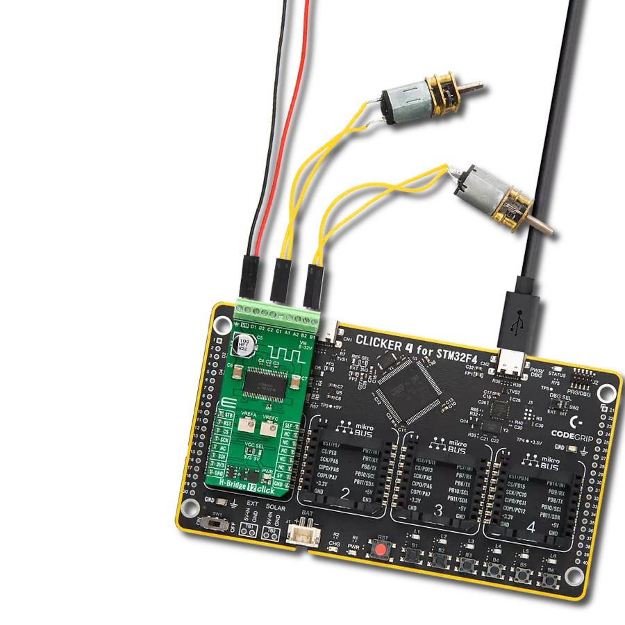
H-Bridge 12 Click is based on the DRV8823, a four-bridge serial interface motor driver from Texas Instruments. Internally, the motor driver consists of four NMOS H-Bridges, a micro-stepping indexer, and various fault-protecting features. The motor driver is fully protected against overcurrent, overtemperature, undervoltage, and comes in a thermally-enhanced package. It can control motors that operate in an 8V to 32V voltage range, with up to 1.5A of current per winding. For this, it uses an internal charge pump for the gate drives. Eight current levels set through the serial interface allow micro-stepping with bipolar stepper motors. H-Bridge 12 Click uses a simple 3-Wire SPI
serial interface to communicate with the host MCU. In addition, this Click board™ uses some other pins from the mikroBUS™ socket, such as the RST pin for the device reset. The motor driver outputs can be turned off with the STB's pin LOW logic state while resetting the serial interface. Another neat feature is sleep, which can be activated with logic LOW on the SLP pin of the mikroBUS™ socket. There are two precision potentiometers labeled VREFA and VREFC. The VREFA supplies the referent voltage for setting the current trip threshold for bridges A and B, while the VREFC supplies the referent voltage for setting the current trip threshold for bridges C and D.
H-Bridge 12 Click comes with screw terminals for connecting an external motor power supply, labeled with ground and VM. The motors can be connected to 8 terminals appropriately labeled for every single motor output channel. The motor driver supports Brushed DC, Brushless DC, and Stepper motors. This Click board™ can operate with either 3.3V or 5V logic voltage levels selected via the VCC SEL jumper. This way, both 3.3V and 5V capable MCUs can use the communication lines properly. Also, this Click board™ comes equipped with a library containing easy-to-use functions and an example code that can be used as a reference for further development.

Features overview
Development board
Clicker 4 for STM32F4 is a compact development board designed as a complete solution that you can use to quickly build your own gadgets with unique functionalities. Featuring an STM32F407VGT6 MCU, four mikroBUS™ sockets for Click boards™ connectivity, power management, and more, it represents a perfect solution for the rapid development of many different types of applications. At its core is an STM32F407VGT6 MCU, a powerful microcontroller by STMicroelectronics based on the high-performance
Arm® Cortex®-M4 32-bit processor core operating at up to 168 MHz frequency. It provides sufficient processing power for the most demanding tasks, allowing Clicker 4 to adapt to any specific application requirements. Besides two 1x20 pin headers, four improved mikroBUS™ sockets represent the most distinctive connectivity feature, allowing access to a huge base of Click boards™, growing on a daily basis. Each section of Clicker 4 is clearly marked, offering an intuitive and clean interface. This makes working with the
development board much simpler and, thus, faster. The usability of Clicker 4 doesn’t end with its ability to accelerate the prototyping and application development stages: it is designed as a complete solution that can be implemented directly into any project, with no additional hardware modifications required. Four mounting holes [4.2mm/0.165”] at all four corners allow simple installation by using mounting screws.

Microcontroller Overview
MCU Card / MCU

Architecture
ARM Cortex-M4
MCU Memory (KB)
10
Silicon Vendor
STMicroelectronics
Pin count
100
RAM (Bytes)
100
You complete me!
Accessories
DC Gear Motor - 430RPM (3-6V) represents an all-in-one combination of a motor and gearbox, where the addition of gear leads to a reduction of motor speed while increasing the torque output. This gear motor has a spur gearbox, making it a highly reliable solution for applications with lower torque and speed requirements. The most critical parameters for gear motors are speed, torque, and efficiency, which are, in this case, 520RPM with no load and 430RPM at maximum efficiency, alongside a current of 60mA and a torque of 50g.cm. Rated for a 3-6V operational voltage range and clockwise/counterclockwise rotation direction, this motor represents an excellent solution for many functions initially performed by brushed DC motors in robotics, medical equipment, electric door locks, and much more.

Used MCU Pins
mikroBUS™ mapper
Take a closer look
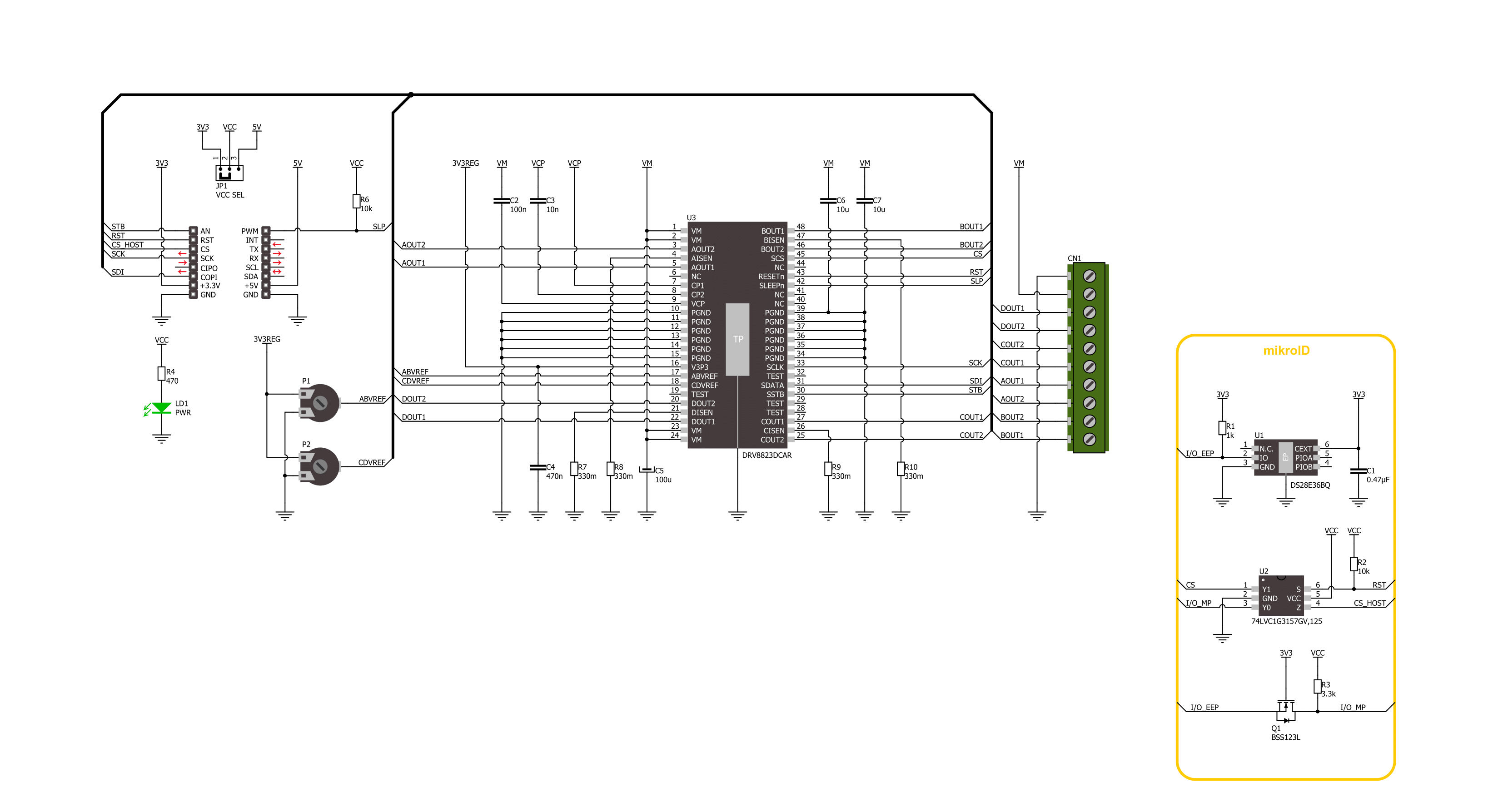
Click board™ Schematic
Step by step
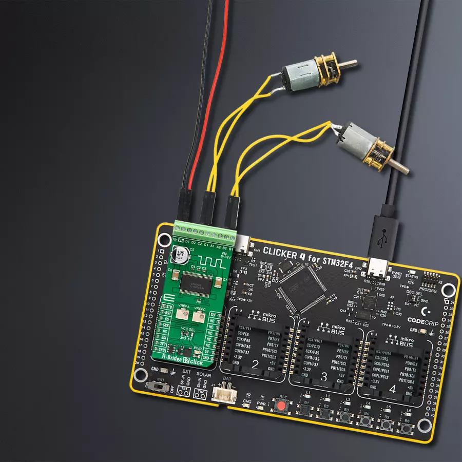
Project assembly

Start by selecting your development board and Click board™. Begin with the Clicker 4 for STM32F4 as your development board.


Software Support
Library Description
This library contains API for H-Bridge 12 Click driver.
Key functions:
hbridge12_write_config- H-Bridge 12 write settings function.hbridge12_set_current_scale- H-Bridge 12 set current scale function.hbridge12_turn_clockwise- H-Bridge 12 turn motor clockwise function.
Open Source
Code example
The complete application code and a ready-to-use project are available through the NECTO Studio Package Manager for direct installation in the NECTO Studio. The application code can also be found on the MIKROE GitHub account.
/*!
 * @file main.c
 * @brief H-Bridge 12 Click example
 *
 * # Description
 * This example demonstrates the use of the H-Bridge 12 Click board by
 * driving the motor connected to OUT A and OUT B, in both directions with braking and freewheeling.
 *
 * The demo application is composed of two sections :
 *
 * ## Application Init
 * Initializes the driver and performs the Click default configuration.
 *
 * ## Application Task
 * Driving motor in both directions for 5 seconds with a motor braking and freewheeling in between.
 *
 * @author Stefan Ilic
 *
 */

#include "board.h"
#include "log.h"
#include "hbridge12.h"

static hbridge12_t hbridge12;
static log_t logger;

void application_init ( void )
{
    log_cfg_t log_cfg;  /**< Logger config object. */
    hbridge12_cfg_t hbridge12_cfg;  /**< Click config object. */

    /**
     * Logger initialization.
     * Default baud rate: 115200
     * Default log level: LOG_LEVEL_DEBUG
     * @note If USB_UART_RX and USB_UART_TX
     * are defined as HAL_PIN_NC, you will
     * need to define them manually for log to work.
     * See @b LOG_MAP_USB_UART macro definition for detailed explanation.
     */
    LOG_MAP_USB_UART( log_cfg );
    log_init( &logger, &log_cfg );
    log_info( &logger, " Application Init " );

    // Click initialization.
    hbridge12_cfg_setup( &hbridge12_cfg );
    HBRIDGE12_MAP_MIKROBUS( hbridge12_cfg, MIKROBUS_1 );
    if ( SPI_MASTER_ERROR == hbridge12_init( &hbridge12, &hbridge12_cfg ) )
    {
        log_error( &logger, " Communication init." );
        for ( ; ; );
    }

    if ( HBRIDGE12_ERROR == hbridge12_default_cfg ( &hbridge12 ) )
    {
        log_error( &logger, " Default configuration." );
        for ( ; ; );
    }

    log_info( &logger, " Application Task " );
}

void application_task ( void )
{
    log_printf( &logger, " Turning motor counterclockwise \r\n" );
    hbridge12_turn_counterclockwise( &hbridge12, HBRIDGE12_AB_BRIDGE_SEL );
    Delay_ms ( 1000 );
    Delay_ms ( 1000 );
    Delay_ms ( 1000 );
    Delay_ms ( 1000 );
    Delay_ms ( 1000 );

    log_printf( &logger, " Turning motor brake on \r\n" );
    hbridge12_turn_brake_on( &hbridge12, HBRIDGE12_AB_BRIDGE_SEL );
    Delay_ms ( 1000 );
    Delay_ms ( 1000 );
    Delay_ms ( 1000 );
    Delay_ms ( 1000 );
    Delay_ms ( 1000 );

    log_printf( &logger, " Turning motor clockwise \r\n" );
    hbridge12_turn_clockwise( &hbridge12, HBRIDGE12_AB_BRIDGE_SEL );
    Delay_ms ( 1000 );
    Delay_ms ( 1000 );
    Delay_ms ( 1000 );
    Delay_ms ( 1000 );
    Delay_ms ( 1000 );

    log_printf( &logger, " Motor freewheeling \r\n" );
    hbridge12_freewheeling_on( &hbridge12, HBRIDGE12_AB_BRIDGE_SEL );
    Delay_ms ( 1000 );
    Delay_ms ( 1000 );
    Delay_ms ( 1000 );
    Delay_ms ( 1000 );
    Delay_ms ( 1000 );
}

int main ( void )
{
    /* Do not remove this line or clock might not be set correctly. */
    #ifdef PREINIT_SUPPORTED
    preinit();
    #endif

    application_init( );

    for ( ; ; )
    {
        application_task( );
    }

    return 0;
}

// ------------------------------------------------------------------------ END
Additional Support
Resources
Category:Brushed


