Achieve precise and natural control using COM-09032 and STM32F407VGT6
Level up your HMI experience

Published Dec 29, 2023
Click board™
THUMBSTICK Click
Dev. board
Clicker 4 for STM32F4
Compiler
NECTO Studio
MCU
STM32F407VGT6
Achieve precise analog control for gaming consoles and controllers, enhancing the gameplay experience, or applications that require accurate control inputs, such as robotics or drone navigation systems
A
A
Hardware Overview
How does it work?
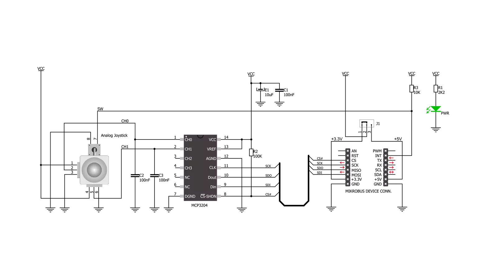
Thumbstick Click is based on the COM-09032, a high-quality 2-axis analog-type thumbstick from Sparkfun. This type of thumbstick has a self-centering feature (spring return) that allows it to center itself the moment when you release it. It also contains a comfortable cup-type black knob/cap, which gives the feel of a thumbstick, making it very similar to the 'analog' joysticks used on joypads on popular gaming consoles like PSP joysticks. This feature makes it suitable for numerous applications as a human-machine interface. It comprises two 10kΩ potentiometers, one for up/down and another for left/right direction, used as dual adjustable voltage dividers providing 2-axis analog input in a control stick form. With the thumbstick fully
assembled and functioning, the voltage will follow the motion of the thumbstick as it is moved around. The measurements of the potentiometer resistance change are needed to read the thumbstick's physical position. That's why the MCP3204, a 12-bit A/D converter with conversion rates of up to 100ksps from Microchip, connects the thumbstick with mikroBUS™ using a simple serial interface compatible with the SPI protocol to determine the value of the joystick's X and Y. As the MCP3204 has a resolution of 12 bits, the values on each analog channel (axis) can vary from 0 to 4095. So, if the stick is moved on the X axis from one end to the other, the X values will change from 0 to 4095, and a similar thing happens when moved along the
Y axis. The value of the thumbstick staying in its center position is around 2048. Also, the thumbstick has a pushbutton feature that sends an interrupt signal to the host MCU through the INT line of the mikroBUS™ socket. This Click board™ can operate with both 3.3V and 5V logic voltage levels selected via SMD jumper. This way, it is allowed for both 3.3V and 5V capable MCUs to use the communication lines properly. However, the Click board™ comes equipped with a library containing easy-to-use functions and an example code that can be used, as a reference, for further development.

Features overview
Development board
Clicker 4 for STM32F4 is a compact development board designed as a complete solution that you can use to quickly build your own gadgets with unique functionalities. Featuring an STM32F407VGT6 MCU, four mikroBUS™ sockets for Click boards™ connectivity, power management, and more, it represents a perfect solution for the rapid development of many different types of applications. At its core is an STM32F407VGT6 MCU, a powerful microcontroller by STMicroelectronics based on the high-performance
Arm® Cortex®-M4 32-bit processor core operating at up to 168 MHz frequency. It provides sufficient processing power for the most demanding tasks, allowing Clicker 4 to adapt to any specific application requirements. Besides two 1x20 pin headers, four improved mikroBUS™ sockets represent the most distinctive connectivity feature, allowing access to a huge base of Click boards™, growing on a daily basis. Each section of Clicker 4 is clearly marked, offering an intuitive and clean interface. This makes working with the
development board much simpler and, thus, faster. The usability of Clicker 4 doesn’t end with its ability to accelerate the prototyping and application development stages: it is designed as a complete solution that can be implemented directly into any project, with no additional hardware modifications required. Four mounting holes [4.2mm/0.165”] at all four corners allow simple installation by using mounting screws.

Microcontroller Overview
MCU Card / MCU

Architecture
ARM Cortex-M4
MCU Memory (KB)
10
Silicon Vendor
STMicroelectronics
Pin count
100
RAM (Bytes)
100
Used MCU Pins
mikroBUS™ mapper
Take a closer look
Click board™ Schematic
Step by step
Project assembly

Start by selecting your development board and Click board™. Begin with the Clicker 4 for STM32F4 as your development board.


Software Support
Library Description
This library contains API for Thumbstick Click driver.
Key functions:
thumbstick_button_state- Get state of thumbstick button functionthumbstick_get_position- Get thumbstick position by axis function
Open Source
Code example
The complete application code and a ready-to-use project are available through the NECTO Studio Package Manager for direct installation in the NECTO Studio. The application code can also be found on the MIKROE GitHub account.
/*!
 * \file
 * \brief Thumbstick Click example
 *
 * # Description
 * The demo application shows Clickboard axis postioning and button pressed.
 *
 * The demo application is composed of two sections :
 *
 * ## Application Init
 * Initialization of Click board's and log's objects.
 *
 * ## Application Task
 * It reads the position of the thumbstick,
 *  - You will get data on log on every change of thumbstick axis position, or if you hold
 *      thumbstick in one postion it will repeat the same log when timer reaches timeout.
 *  - You will get data on log whenever you press thumbstick button and release it.
 *
 * \author Luka Filipovic
 *
 */
// ------------------------------------------------------------------- INCLUDES

#include "board.h"
#include "log.h"
#include "thumbstick.h"

// ------------------------------------------------------------------ VARIABLES

static thumbstick_t thumbstick;
static log_t logger;


static uint8_t old_butt_state;
static uint8_t button_state;

static thumbstick_position_t old_pos;
static thumbstick_position_t thumbstick_pos;

static uint16_t timer_cnt;
#define TIMER_FLAG 1000

static bool change_state;

// ------------------------------------------------------ APPLICATION FUNCTIONS

void application_init ( void )
{
    log_cfg_t log_cfg;
    thumbstick_cfg_t cfg;

    /**
     * Logger initialization.
     * Default baud rate: 115200
     * Default log level: LOG_LEVEL_DEBUG
     * @note If USB_UART_RX and USB_UART_TX
     * are defined as HAL_PIN_NC, you will
     * need to define them manually for log to work.
     * See @b LOG_MAP_USB_UART macro definition for detailed explanation.
     */
    LOG_MAP_USB_UART( log_cfg );
    log_init( &logger, &log_cfg );
    log_info( &logger, "---- Application Init ----" );

    //  Click initialization.

    thumbstick_cfg_setup( &cfg );
    THUMBSTICK_MAP_MIKROBUS( cfg, MIKROBUS_1 );
    thumbstick_init( &thumbstick, &cfg );

    thumbstick_set_sensitivity( POSTION_SENS_DEFAULT );

    thumbstick_get_position( &thumbstick, &old_pos );
    old_butt_state = thumbstick_button_state( &thumbstick );
    timer_cnt = 0;
    change_state = false;
}

void application_task ( void )
{
    //Button pressed
    button_state = thumbstick_button_state( &thumbstick );

    if ( old_butt_state != button_state )
    {
        if ( button_state == THUMBSTICK_PRESS_BUTTON )
        {
            log_printf( &logger, ">> Button is pressed \r\n" );
            Delay_ms ( 100 );
        }
        else
        {
            log_printf( &logger, ">> Button is released \r\n" );
            Delay_ms ( 100 );
        }
        old_butt_state = button_state;
    }

    //Thumbstick postion
    thumbstick_get_position( &thumbstick, &thumbstick_pos );

    if ( ( old_pos.vertical != thumbstick_pos.vertical ) || ( timer_cnt >= TIMER_FLAG ) )
    {
        if ( thumbstick_pos.vertical == THUMBSTICK_POSITION_TOP )
        {
            log_printf( &logger, ">> TOP \r\n" );
            change_state = true;
        }
        else if ( thumbstick_pos.vertical == THUMBSTICK_POSITION_BOTTOM )
        {
            log_printf( &logger, ">> BOTTOM \r\n" );
            change_state = true;
        }

        old_pos = thumbstick_pos;
    }

    if ( (old_pos.horizontal != thumbstick_pos.horizontal ) || ( timer_cnt >= TIMER_FLAG )  )
    {
        if ( thumbstick_pos.horizontal == THUMBSTICK_POSITION_LEFT )
        {
            log_printf( &logger, ">> LEFT \r\n" );
            change_state = true;
        }
        else if ( thumbstick_pos.horizontal == THUMBSTICK_POSITION_RIGHT )
        {
            log_printf( &logger, ">> RIGHT \r\n" );
            change_state = true;
        }

        old_pos = thumbstick_pos;
    }

    if ( ( timer_cnt >= TIMER_FLAG ) || ( change_state == true )  )
    {
        timer_cnt = 0;
        change_state = false;
    }

    timer_cnt++;
    Delay_ms ( 1 );
}

int main ( void )
{
    /* Do not remove this line or clock might not be set correctly. */
    #ifdef PREINIT_SUPPORTED
    preinit();
    #endif

    application_init( );

    for ( ; ; )
    {
        application_task( );
    }

    return 0;
}


// ------------------------------------------------------------------------ END
Additional Support
Resources
Category:Pushbutton/Switches


