Enhance energy efficiency with MLX75305 and PIC18F2455 by tailoring illumination to the available natural light
Let there be light data
Published Jan 23, 2024
Click board™
Ambient Click
Dev. board
Curiosity HPC
Compiler
NECTO Studio
MCU
PIC18F2455
Unlock the ability to monitor and control environmental conditions effortlessly, making your space more comfortable and energy-efficient
A
A
Hardware Overview
How does it work?
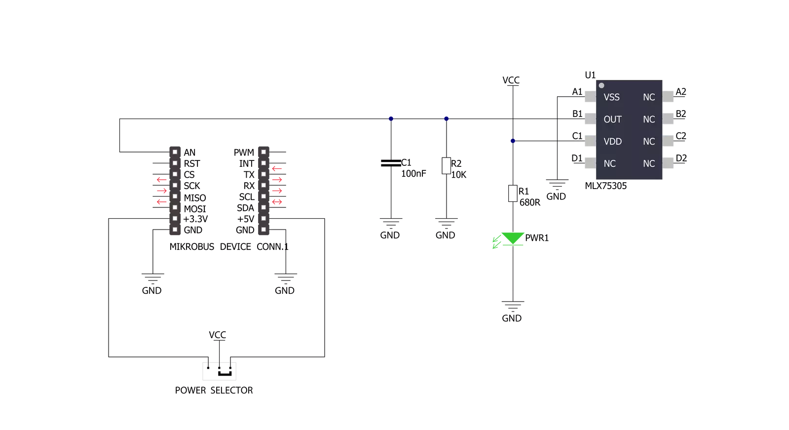
Ambient Click is based on the MLX75305, a light-to-voltage SensorEyeC™ from Melexis Technologies. The MLX75305 is the second member of the SensorEyeC™ series of optical sensors designed for high-volume automotive, industrial, and consumer applications. It includes a photodiode, a trans-impedance amplifier to convert and amplify the photocurrent of the photodiode, and an open drain output buffer stage which gives a voltage value that varies
linearly with incident light, available on the AN pin of the mikroBUS™ socket. An internal configuration like this guarantees stable light responsivity over time and temperature and drastically improves noise behavior compared to discrete photodiode designs. Covering a spectral bandwidth from 500nm up to 1000nm, the MLX75305 maintains ±2% linearity across its whole output voltage range with a typical responsiveness of 70mV/(µW/cm²). Its unique features make it
suitable for measuring ambient light or controlling LED light in LCD backlight dimming applications. This Click board™ can operate with either 3.3V or 5V logic voltage levels selected via the PWR SEL jumper. This way, both 3.3V and 5V capable MCUs can use the communication lines properly. Also, this Click board™ comes equipped with a library containing easy-to-use functions and an example code that can be used as a reference for further development.

Features overview
Development board
Curiosity HPC, standing for Curiosity High Pin Count (HPC) development board, supports 28- and 40-pin 8-bit PIC MCUs specially designed by Microchip for the needs of rapid development of embedded applications. This board has two unique PDIP sockets, surrounded by dual-row expansion headers, allowing connectivity to all pins on the populated PIC MCUs. It also contains a powerful onboard PICkit™ (PKOB), eliminating the need for an external programming/debugging tool, two mikroBUS™ sockets for Click board™ connectivity, a USB connector, a set of indicator LEDs, push button switches and a variable potentiometer. All
these features allow you to combine the strength of Microchip and Mikroe and create custom electronic solutions more efficiently than ever. Each part of the Curiosity HPC development board contains the components necessary for the most efficient operation of the same board. An integrated onboard PICkit™ (PKOB) allows low-voltage programming and in-circuit debugging for all supported devices. When used with the MPLAB® X Integrated Development Environment (IDE, version 3.0 or higher) or MPLAB® Xpress IDE, in-circuit debugging allows users to run, modify, and troubleshoot their custom software and hardware
quickly without the need for additional debugging tools. Besides, it includes a clean and regulated power supply block for the development board via the USB Micro-B connector, alongside all communication methods that mikroBUS™ itself supports. Curiosity HPC development board allows you to create a new application in just a few steps. Natively supported by Microchip software tools, it covers many aspects of prototyping thanks to many number of different Click boards™ (over a thousand boards), the number of which is growing daily.

Microcontroller Overview
MCU Card / MCU

Architecture
PIC
MCU Memory (KB)
24
Silicon Vendor
Microchip
Pin count
28
RAM (Bytes)
2048
Used MCU Pins
mikroBUS™ mapper
Take a closer look
Click board™ Schematic
Step by step
Project assembly

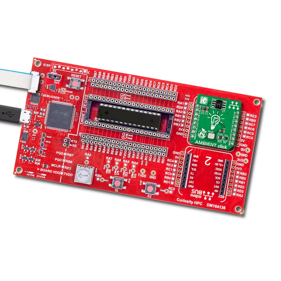
Start by selecting your development board and Click board™. Begin with the Curiosity HPC as your development board.


Track your results in real time
Application Output
1. Application Output - In Debug mode, the 'Application Output' window enables real-time data monitoring, offering direct insight into execution results. Ensure proper data display by configuring the environment correctly using the provided tutorial.

2. UART Terminal - Use the UART Terminal to monitor data transmission via a USB to UART converter, allowing direct communication between the Click board™ and your development system. Configure the baud rate and other serial settings according to your project's requirements to ensure proper functionality. For step-by-step setup instructions, refer to the provided tutorial.

3. Plot Output - The Plot feature offers a powerful way to visualize real-time sensor data, enabling trend analysis, debugging, and comparison of multiple data points. To set it up correctly, follow the provided tutorial, which includes a step-by-step example of using the Plot feature to display Click board™ readings. To use the Plot feature in your code, use the function: plot(*insert_graph_name*, variable_name);. This is a general format, and it is up to the user to replace 'insert_graph_name' with the actual graph name and 'variable_name' with the parameter to be displayed.

Software Support
Library Description
This library contains API for Ambient Click driver.
Key functions:
ambient_read_an_pin_voltage- This function reads results of AD conversion of the AN pin and converts them to proportional voltage levelambient_get_light_intensity- Calculates the light intensity from analog voltage measurement of the Melexis MLX75305 on Ambient Click
Open Source
Code example
The complete application code and a ready-to-use project are available through the NECTO Studio Package Manager for direct installation in the NECTO Studio. The application code can also be found on the MIKROE GitHub account.
/*!
 * \file
 * \brief Ambient Click example
 *
 * # Description
 * This application turns light intensity into voltage.
 *
 * The demo application is composed of two sections :
 *
 * ## Application Init
 * Initialization driver and logger.
 *
 * ## Application Task
 * This is an example which demonstrates the use of Ambient Click board.
 * Ambient Click reads ADC voltage once per second and converts it to light intensity [ uW/cm2 ].
 * Results are being sent to the USB UART where you can track their changes.
 *
 * \author MikroE Team
 *
 */

#include "board.h"
#include "log.h"
#include "ambient.h"

static ambient_t ambient;
static log_t logger;

void application_init ( void )
{
    log_cfg_t log_cfg;
    ambient_cfg_t cfg;

    /**
     * Logger initialization.
     * Default baud rate: 115200
     * Default log level: LOG_LEVEL_DEBUG
     * @note If USB_UART_RX and USB_UART_TX
     * are defined as HAL_PIN_NC, you will
     * need to define them manually for log to work.
     * See @b LOG_MAP_USB_UART macro definition for detailed explanation.
     */
    LOG_MAP_USB_UART( log_cfg );
    log_init( &logger, &log_cfg );
    log_info( &logger, " Application Init " );

    // Click initialization.
    ambient_cfg_setup( &cfg );
    AMBIENT_MAP_MIKROBUS( cfg, MIKROBUS_1 );
    ambient_init( &ambient, &cfg );

    log_info( &logger, " Application Task " );
}

void application_task ( void )
{
    uint16_t light_intensity = ambient_get_light_intensity( &ambient );
    log_printf( &logger, " Light Intensity: %u uW/cm2\r\n\n", light_intensity );
    Delay_ms ( 1000 );
}

int main ( void )
{
    /* Do not remove this line or clock might not be set correctly. */
    #ifdef PREINIT_SUPPORTED
    preinit();
    #endif

    application_init( );

    for ( ; ; )
    {
        application_task( );
    }

    return 0;
}


// ------------------------------------------------------------------------ END
Additional Support
Resources
Category:Optical


