Accurately measure bidirectional current flows with MCR1101-20-5 and PIC18F57Q43
Precision beyond limits!

Published Feb 13, 2024
Click board™
AMR Current Click
Dev Board
Curiosity Nano with PIC18F57Q43
Compiler
NECTO Studio
MCU
PIC18F57Q43
Utilizing advanced AMR sensor tech, our solution offers precision with minimal noise, revealing current trends and optimizing system performance
A
A
Hardware Overview
How does it work?
AMR Current Click is based on the MCR1101-20-5, an AMR-based integrated current sensor from ACEINNA. The device has superior range and accuracy (0.6% typical total error at 25°C) and 2.0% max error over temperature. It also features a Superior Frequency Response - 1.5 MHz (typically 3dB BW) and a Fast output response time (300ns typical) with a Low Primary Resistance (0.9 mΩ). The MCR1101-20-5 current sensor is factory-calibrated to achieve low offset error and provide a precise analog voltage output that is linearly proportional to the conduction current (AC or DC) with sensitivity (mV/A) compatible with A/D converters and analog control loops in power systems. The VOC pin is connected directly to VOC (Reset) pin on mikroBUS™. The voltage on this pin defines the overcurrent detection OCD threshold level. Briefly driving this pin to VCC resets and rearms OCD circuit. The AMR sensor device structure is designed to eliminate sensitivity to stray and common mode magnetic fields. Anisotropic magnetoresistance (AMR) uses a common material, Permalloy, to act as a magnetometer. Permalloy is an alloy containing roughly 80% nickel and 20% iron. The alloy's resistance depends on the angle between the magnetization and the direction of current flow. In
a magnetic field, magnetization rotates toward the direction of the magnetic field, and the rotation angle depends on the external field's magnitude. In a current sensor application, two of these resistors are connected in a Wheatstone bridge configuration to permit the measurement of the magnitude of the magnetic field produced by the current. AMR properties are well-behaved when the film's magnetic domains are aligned in the same direction. This configuration ensures high sensitivity, good repeatability, and minimal hysteresis. The film is deposited during fabrication in a strong magnetic field that sets the magnetization vector's preferred orientation, or "easy" axis, in the Permalloy resistors. AMR has better sensitivity than other methods and reasonably good temperature stability. The AMR sensor has a sensitivity that is approximately a linear function of temperature. The AMR Current has fast and accurate overcurrent fault detection circuitry. The overcurrent fault threshold (I ) is user-configurable via an external resistor divider (FLT INT) and supports a range of 120% to 200% of the full-scale primary input (IP). The sensor resistors are biased to the VCC supply voltage and produce a ratiometric differential voltage to VCC. This configuration is suited to applications where the
A-to-D or other circuitry receiving the current sensor output signals are biased by and ratiometric to the same supply voltage as the current sensor. The ratiometric configuration provides increased gain and resolution compared to fixed gain. The Click board detects the current by measuring the magnetic field generated by that current. Therefore it's important to consider the effect of externally generated magnetic fields, whether from another current flowing in the system, a magnet, or an electromagnetic component. The AMR Current click also features the MCP3221 AST, an A/D converter with a 12-bit resolution. This device provides one single-ended input with low power consumption. The AMR Current click can directly transfer the input from analog to digital because it contains the A/D converter. Also featured on the AMR Current click is the R7 resistor, which can be used if the communication goes directly to the mikroBUS™ device and is not used if you use the A/D converter (MCP3221 AST). This Click can be used for various purposes, including server, telecom & industrial PWR supplies, power aggregation, over-current protection, motor balance, remote device monitoring, and home automation control & IOT remote sensing.


Features overview
Development board
PIC18F57Q43 Curiosity Nano evaluation kit is a cutting-edge hardware platform designed to evaluate microcontrollers within the PIC18-Q43 family. Central to its design is the inclusion of the powerful PIC18F57Q43 microcontroller (MCU), offering advanced functionalities and robust performance. Key features of this evaluation kit include a yellow user LED and a responsive
mechanical user switch, providing seamless interaction and testing. The provision for a 32.768kHz crystal footprint ensures precision timing capabilities. With an onboard debugger boasting a green power and status LED, programming and debugging become intuitive and efficient. Further enhancing its utility is the Virtual serial port (CDC) and a debug GPIO channel (DGI
GPIO), offering extensive connectivity options. Powered via USB, this kit boasts an adjustable target voltage feature facilitated by the MIC5353 LDO regulator, ensuring stable operation with an output voltage ranging from 1.8V to 5.1V, with a maximum output current of 500mA, subject to ambient temperature and voltage constraints.

Microcontroller Overview
MCU Card / MCU

Architecture
PIC
MCU Memory (KB)
128
Silicon Vendor
Microchip
Pin count
48
RAM (Bytes)
8196
You complete me!
Accessories
Curiosity Nano Base for Click boards is a versatile hardware extension platform created to streamline the integration between Curiosity Nano kits and extension boards, tailored explicitly for the mikroBUS™-standardized Click boards and Xplained Pro extension boards. This innovative base board (shield) offers seamless connectivity and expansion possibilities, simplifying experimentation and development. Key features include USB power compatibility from the Curiosity Nano kit, alongside an alternative external power input option for enhanced flexibility. The onboard Li-Ion/LiPo charger and management circuit ensure smooth operation for battery-powered applications, simplifying usage and management. Moreover, the base incorporates a fixed 3.3V PSU dedicated to target and mikroBUS™ power rails, alongside a fixed 5.0V boost converter catering to 5V power rails of mikroBUS™ sockets, providing stable power delivery for various connected devices.

Used MCU Pins
mikroBUS™ mapper
Take a closer look
Schematic

Step by step
Project assembly

Start by selecting your development board and Click board™. Begin with the Curiosity Nano with PIC18F57Q43 as your development board.


Track your results in real time
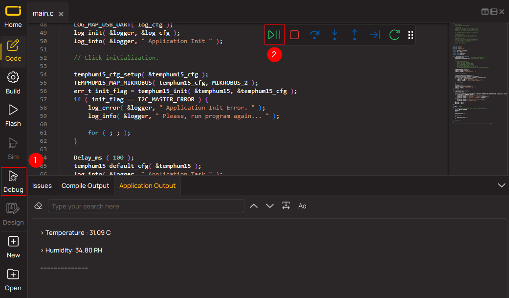
Application Output via Debug Mode
1. Once the code example is loaded, pressing the "DEBUG" button initiates the build process, programs it on the created setup, and enters Debug mode.
2. After the programming is completed, a header with buttons for various actions within the IDE becomes visible. Clicking the green "PLAY" button starts reading the results achieved with the Click board™. The achieved results are displayed in the Application Output tab.
Software Support
Library Description
This library contains API for AMR Current Click driver.
Key functions:
amrcurent_generic_write- This function writes data to the desired registeramrcurent_generic_read- This function reads data from the desired registeramrcurrent_read_value- This function read value
Open Source
Code example
This example can be found in NECTO Studio. Feel free to download the code, or you can copy the code below.
/*!
 * \file
 * \brief AMRCurent Click example
 *
 * # Description
 * This application integrated bi-directional analog output current sensors.
 *
 * The demo application is composed of two sections :
 *
 * ## Application Init
 * Initializations driver init.
 *
 * ## Application Task
 * Reading ADC data and converted current mA data from device and logs it to device.
 *

 *
 * \author MikroE Team
 *
 */
// ------------------------------------------------------------------- INCLUDES

#include "board.h"
#include "log.h"
#include "amrcurrent.h"

// ------------------------------------------------------------------ VARIABLES

static amrcurent_t amrcurent;
static log_t logger;
uint16_t read_adc_val;
float read_curr_val;

// ------------------------------------------------------ APPLICATION FUNCTIONS

void application_init ( void )
{
    log_cfg_t log_cfg;
    amrcurent_cfg_t cfg;

    /**
     * Logger initialization.
     * Default baud rate: 115200
     * Default log level: LOG_LEVEL_DEBUG
     * @note If USB_UART_RX and USB_UART_TX
     * are defined as HAL_PIN_NC, you will
     * need to define them manually for log to work.
     * See @b LOG_MAP_USB_UART macro definition for detailed explanation.
     */
    LOG_MAP_USB_UART( log_cfg );
    log_init( &logger, &log_cfg );
    log_info( &logger, "---- Application Init ----" );

    //  Click initialization.

    amrcurent_cfg_setup( &cfg );
    AMRCURENT_MAP_MIKROBUS( cfg, MIKROBUS_1 );
    amrcurent_init( &amrcurent, &cfg );
}

void application_task ( void )
{
    //  Task implementation.

    read_adc_val = amrcurrent_read_value ( &amrcurent );
    log_printf( &logger, " - ADC value: %d\r\n ", read_adc_val );

    Delay_ms( 100 );

    read_curr_val = amrcurrent_get_current (  &amrcurent );
    log_printf( &logger, " - Current value: %f\r\n ", read_curr_val );

    Delay_ms( 5000 );
}

void main ( void )
{
    application_init( );

    for ( ; ; )
    {
        application_task( );
    }
}

// ------------------------------------------------------------------------ END


