Ensure precise voltage management at your fingertips with KMR221 and PIC18F57Q43
Switching voltage, one button press at a time
Published Feb 13, 2024
Click board™
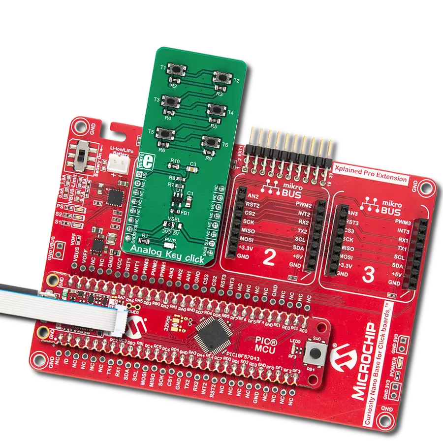
Analog Key Click
Dev. board
Curiosity Nano with PIC18F57Q43
Compiler
NECTO Studio
MCU
PIC18F57Q43
This analog keyboard, equipped with six tactile pushbuttons, allows users to select from a range of voltage levels with unparalleled precision, making it ideal for diverse electrical applications
A
A
Hardware Overview
How does it work?
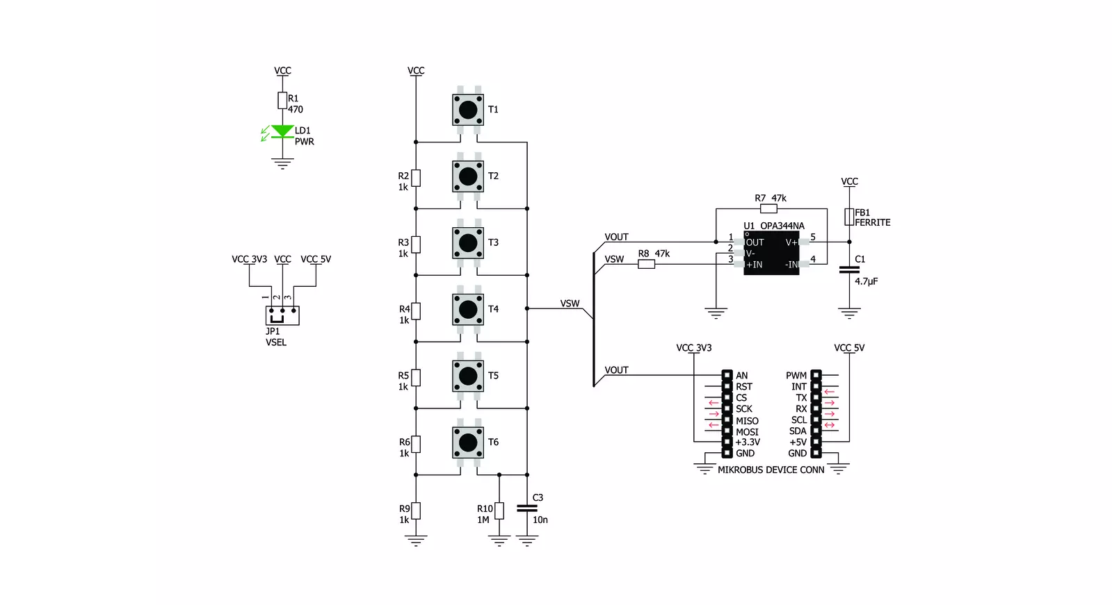
Analog Key Click is based on the KMR221, a high-quality SPST switch from C&K. These buttons are rated to endure up to 300,000 switching cycles and have very low ON resistance of less than 100 mΩ. The buttons are rubberized and have a pleasant tactile feel when pressed. By pressing a button, the respective connection point becomes redirected to the input of the OPA344, a low-power operational amplifier from Texas Instruments, which is configured to work with the unity gain, forming a buffer for the input of the microcontroller (MCU). This prevents changes of the impedance at the MCU input pin, as well as a limited amount of ESD protection. By
substituting the voltage divider resistors with two equivalent resistances (RE1 for the upper set of resistors, and RE2 for the lower set of resistors) the principle can be understood even better: when the top button is pressed (T1), the equivalent RE1 resistance will be 0 Ω, so regardless of the RE2 resistance, the voltage at the AN pin will be equal to VCC. When the second button (T2) is pressed, the equivalent RE1 resistance will be 1 kΩ, while the RE2 resistance will be 5K. The VCC voltage for the voltage divider can be selected using the SMD jumper on the Click board™, labeled as VSEL. This jumper selects either a 3.3V or 5V mikroBUS™ power rail as the VCC source. Since there are many
MCUs that cannot tolerate 5V on their pins, the VSEL position is set to 3.3V by default. However, if the 5V operation is required for specific application, it is enough to move the position of the VSEL jumper to the 5V position. The selected output voltage appears at the AN pin of the mikroBUS™, labeled as VO on Analog Key click. It can be then sampled by the A/D converter of the MCU and used to control a device. Since Analog Key click requires just a single pin for its operation, it is perfectly suited for applications where the pin count restriction is a big problem.


Features overview
Development board
PIC18F57Q43 Curiosity Nano evaluation kit is a cutting-edge hardware platform designed to evaluate microcontrollers within the PIC18-Q43 family. Central to its design is the inclusion of the powerful PIC18F57Q43 microcontroller (MCU), offering advanced functionalities and robust performance. Key features of this evaluation kit include a yellow user LED and a responsive
mechanical user switch, providing seamless interaction and testing. The provision for a 32.768kHz crystal footprint ensures precision timing capabilities. With an onboard debugger boasting a green power and status LED, programming and debugging become intuitive and efficient. Further enhancing its utility is the Virtual serial port (CDC) and a debug GPIO channel (DGI
GPIO), offering extensive connectivity options. Powered via USB, this kit boasts an adjustable target voltage feature facilitated by the MIC5353 LDO regulator, ensuring stable operation with an output voltage ranging from 1.8V to 5.1V, with a maximum output current of 500mA, subject to ambient temperature and voltage constraints.

Microcontroller Overview
MCU Card / MCU

Architecture
PIC
MCU Memory (KB)
128
Silicon Vendor
Microchip
Pin count
48
RAM (Bytes)
8196
You complete me!
Accessories
Curiosity Nano Base for Click boards is a versatile hardware extension platform created to streamline the integration between Curiosity Nano kits and extension boards, tailored explicitly for the mikroBUS™-standardized Click boards and Xplained Pro extension boards. This innovative base board (shield) offers seamless connectivity and expansion possibilities, simplifying experimentation and development. Key features include USB power compatibility from the Curiosity Nano kit, alongside an alternative external power input option for enhanced flexibility. The onboard Li-Ion/LiPo charger and management circuit ensure smooth operation for battery-powered applications, simplifying usage and management. Moreover, the base incorporates a fixed 3.3V PSU dedicated to target and mikroBUS™ power rails, alongside a fixed 5.0V boost converter catering to 5V power rails of mikroBUS™ sockets, providing stable power delivery for various connected devices.

Used MCU Pins
mikroBUS™ mapper
Take a closer look
Click board™ Schematic
Step by step
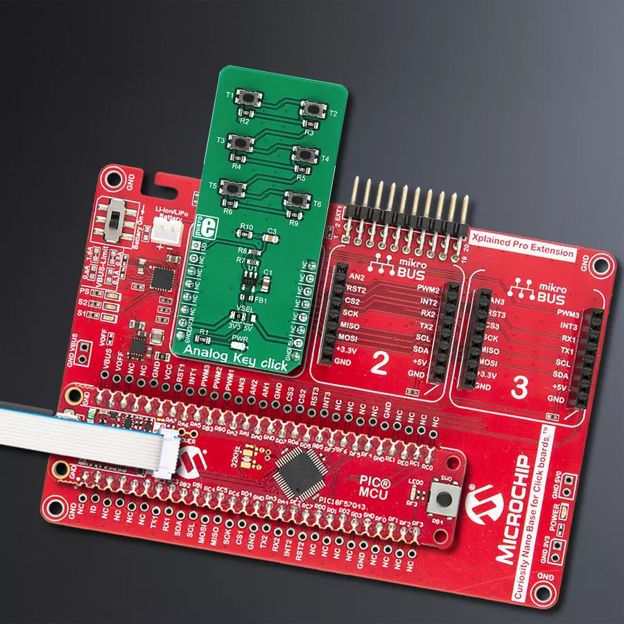
Project assembly

Start by selecting your development board and Click board™. Begin with the Curiosity Nano with PIC18F57Q43 as your development board.


Software Support
Library Description
This library contains API for Analog Key Click driver.
Key functions:
analogkey_get_key- This function returns which button is pressed.analogkey_set_resolution- This function sets the resolution.
Open Source
Code example
The complete application code and a ready-to-use project are available through the NECTO Studio Package Manager for direct installation in the NECTO Studio. The application code can also be found on the MIKROE GitHub account.
/*!
 * \file
 * \brief AnalogKey Click example
 *
 * # Description
 * This application logs what button is pressed.
 *
 * The demo application is composed of two sections :
 *
 * ## Application Init
 * Initializes driver.
 *
 * ## Application Task
 * Reads ADC value and detects which button is pressed based on that value.
 *
 *
 * \author Nemanja Medakovic
 *
 */
// ------------------------------------------------------------------- INCLUDES

#include "board.h"
#include "log.h"
#include "analogkey.h"

#define ANALOGKEY_N_SAMPLES  50

// ------------------------------------------------------------------ VARIABLES

static analogkey_t analogkey;
static log_t logger;

// ------------------------------------------------------ APPLICATION FUNCTIONS

void application_init ( void )
{
    log_cfg_t log_cfg;
    analogkey_cfg_t cfg;

    /**
     * Logger initialization.
     * Default baud rate: 115200
     * Default log level: LOG_LEVEL_DEBUG
     * @note If USB_UART_RX and USB_UART_TX
     * are defined as HAL_PIN_NC, you will
     * need to define them manually for log to work.
     * See @b LOG_MAP_USB_UART macro definition for detailed explanation.
     */
    LOG_MAP_USB_UART( log_cfg );
    log_init( &logger, &log_cfg );
    log_info( &logger, "---- Application Init... ----" );

    analogkey_cfg_setup( &cfg );
    ANALOGKEY_MAP_MIKROBUS( cfg, MIKROBUS_1 );
    if ( analogkey_init( &analogkey, &cfg ) == ADC_ERROR )
    {
        log_info( &logger, "---- Application Init Error. ----" );
        log_info( &logger, "---- Please, run program again... ----" );

        for ( ; ; );
    }
    log_info( &logger, "---- Application Init Done. ----\n" );
}

void application_task ( void )
{
    float an_voltage = 0;
    analogkey_key_id_t key;
    float an_average = 0;

    an_voltage = analogkey_read_voltage( &analogkey );

    if ( an_voltage > 0.2 )
    {
        an_average += an_voltage / ANALOGKEY_N_SAMPLES;
        for ( uint8_t cnt = 0; cnt < ANALOGKEY_N_SAMPLES - 1; cnt++ )
        {
            an_voltage = analogkey_read_voltage( &analogkey );

            an_average += an_voltage / ANALOGKEY_N_SAMPLES;
        }
    }

    if ( ( key = analogkey_get_key( &analogkey, an_average ) ) != ANALOGKEY_TOUCH_KEY_NONE )
    {
        log_printf( &logger, " T%u is pressed.\r\n", (uint16_t)key );

        while ( analogkey_read_voltage( &analogkey ) > 0.2 ) {
             Delay_ms ( 1 );
        }

        log_printf( &logger, " T%u is released.\r\n", (uint16_t)key );
        Delay_ms ( 10 );
    }
}

int main ( void )
{
    /* Do not remove this line or clock might not be set correctly. */
    #ifdef PREINIT_SUPPORTED
    preinit();
    #endif

    application_init( );

    for ( ; ; )
    {
        application_task( );
    }

    return 0;
}


// ------------------------------------------------------------------------ END
Additional Support
Resources
Category:Pushbutton/Switches


