Create the ultimate magnet-angle sensing solution with AS5048A and ATmega328P
360-degree accuracy

Published Feb 14, 2024
Click board™
MAGNETO Click
Dev. board
Arduino UNO Rev3
Compiler
NECTO Studio
MCU
ATmega328P
Experience unparalleled precision and control with our absolute position measurement solution, providing accurate and real-time tracking of magnet rotation angles for enhanced robotics, navigation, and industrial automation applications
A
A
Hardware Overview
How does it work?
Magneto Click is based on the AS5048A, a 360° magnetic Hall sensor system from ams AG, manufactured in a CMOS process and used to measure the magnetic field components perpendicular to the surface of the chip. The integrated Hall sensors are placed around the center of the AS5048A and deliver a voltage representation of the magnetic flux. Through sigma-delta ADC and Digital Signal-Processing (DSP) algorithms, the AS5048A provides accurate high-resolution absolute angular position information of a small, diametrically magnetized (two-pole) standard magnet. The calculation is executed by CORDIC, which calculates the angle and the magnitude of the Hall array signals. DSP also provides information on the magnet
movements towards or away from the sensor surface on the z-axis. The AS5048A is pre-programmed as an SPI interface, with a PWM output signal, available on the INT pin of the mikroBUS™ socket in 12-bit format and provides a 14-bit binary code representing the magnet's angular position. It uses self-calibration methods to eliminate signal offset and sensitivity drifts. Different magnet diameters and magnetic inputs (NeFeB, SmCo, and alternative magnet materials such as hard ferrites) are possible depending on the system requirements. Also, the zero magnet position can be programmed through an SPI interface. The AS5048A uses one-time programmable (OTP) fuses for permanent programming of the user settings, with the
possible programming verification over a simple digital readout of the OTP content. It should be noted that the sensor tolerates misalignment, air gap variations, temperature variations, and as well external magnetic fields. This robustness and wide temperature range of the AS5048A makes it ideal for rotation angle sensing in harsh industrial and medical environments. This Click board™ can be operated only with a 5V logic voltage level. The board must perform appropriate logic voltage level conversion before using MCUs with different logic levels. However, the Click board™ comes equipped with a library containing functions and an example code that can be used as a reference for further development.

Features overview
Development board
Arduino UNO is a versatile microcontroller board built around the ATmega328P chip. It offers extensive connectivity options for various projects, featuring 14 digital input/output pins, six of which are PWM-capable, along with six analog inputs. Its core components include a 16MHz ceramic resonator, a USB connection, a power jack, an
ICSP header, and a reset button, providing everything necessary to power and program the board. The Uno is ready to go, whether connected to a computer via USB or powered by an AC-to-DC adapter or battery. As the first USB Arduino board, it serves as the benchmark for the Arduino platform, with "Uno" symbolizing its status as the
first in a series. This name choice, meaning "one" in Italian, commemorates the launch of Arduino Software (IDE) 1.0. Initially introduced alongside version 1.0 of the Arduino Software (IDE), the Uno has since become the foundational model for subsequent Arduino releases, embodying the platform's evolution.

Microcontroller Overview
MCU Card / MCU

Architecture
AVR
MCU Memory (KB)
32
Silicon Vendor
Microchip
Pin count
28
RAM (Bytes)
2048
You complete me!
Accessories
Click Shield for Arduino UNO has two proprietary mikroBUS™ sockets, allowing all the Click board™ devices to be interfaced with the Arduino UNO board without effort. The Arduino Uno, a microcontroller board based on the ATmega328P, provides an affordable and flexible way for users to try out new concepts and build prototypes with the ATmega328P microcontroller from various combinations of performance, power consumption, and features. The Arduino Uno has 14 digital input/output pins (of which six can be used as PWM outputs), six analog inputs, a 16 MHz ceramic resonator (CSTCE16M0V53-R0), a USB connection, a power jack, an ICSP header, and reset button. Most of the ATmega328P microcontroller pins are brought to the IO pins on the left and right edge of the board, which are then connected to two existing mikroBUS™ sockets. This Click Shield also has several switches that perform functions such as selecting the logic levels of analog signals on mikroBUS™ sockets and selecting logic voltage levels of the mikroBUS™ sockets themselves. Besides, the user is offered the possibility of using any Click board™ with the help of existing bidirectional level-shifting voltage translators, regardless of whether the Click board™ operates at a 3.3V or 5V logic voltage level. Once you connect the Arduino UNO board with our Click Shield for Arduino UNO, you can access hundreds of Click boards™, working with 3.3V or 5V logic voltage levels.

Used MCU Pins
mikroBUS™ mapper
Take a closer look
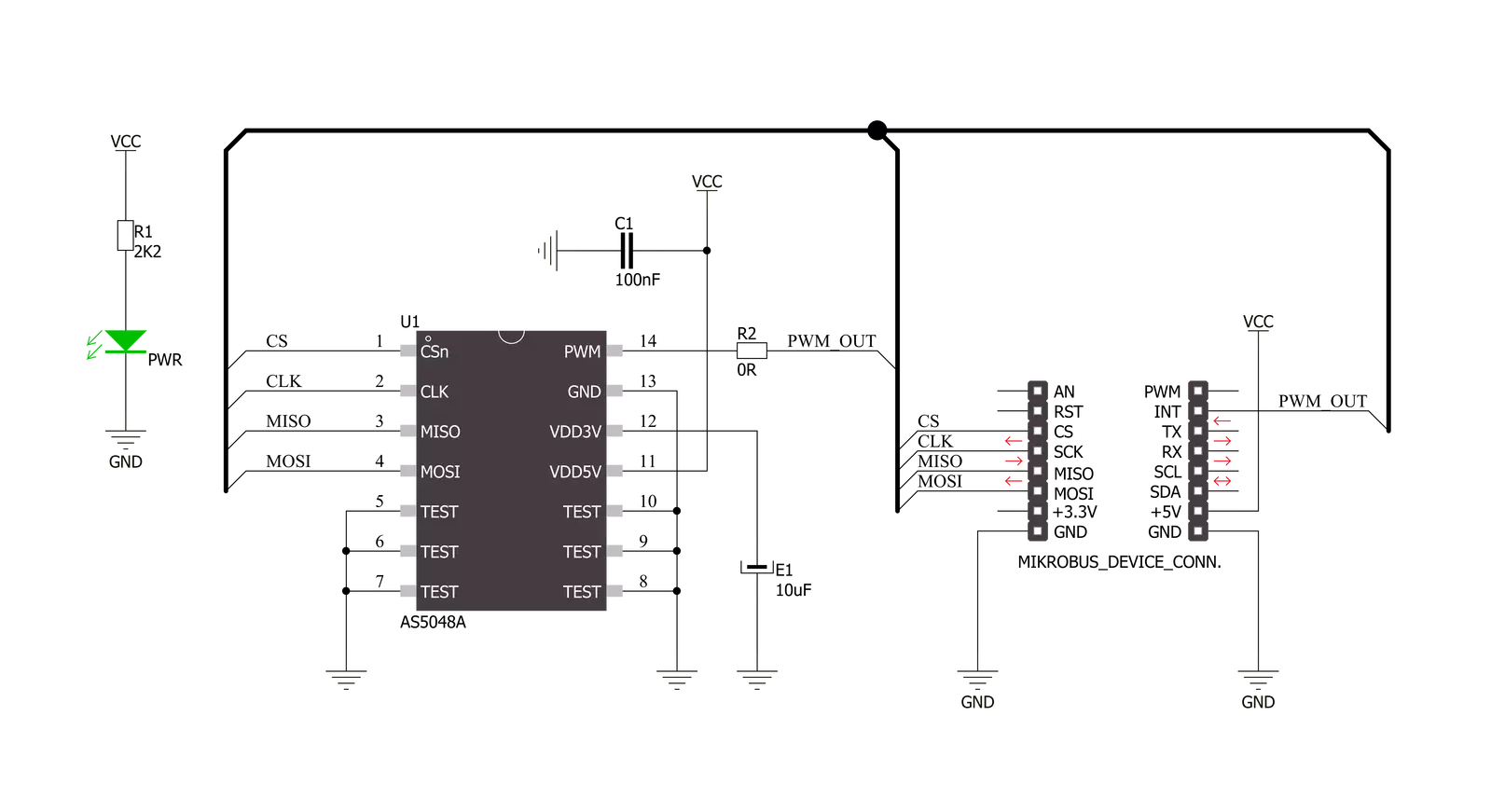
Click board™ Schematic
Step by step
Project assembly

Start by selecting your development board and Click board™. Begin with the Arduino UNO Rev3 as your development board.


Track your results in real time
Application Output
1. Application Output - In Debug mode, the 'Application Output' window enables real-time data monitoring, offering direct insight into execution results. Ensure proper data display by configuring the environment correctly using the provided tutorial.

2. UART Terminal - Use the UART Terminal to monitor data transmission via a USB to UART converter, allowing direct communication between the Click board™ and your development system. Configure the baud rate and other serial settings according to your project's requirements to ensure proper functionality. For step-by-step setup instructions, refer to the provided tutorial.

3. Plot Output - The Plot feature offers a powerful way to visualize real-time sensor data, enabling trend analysis, debugging, and comparison of multiple data points. To set it up correctly, follow the provided tutorial, which includes a step-by-step example of using the Plot feature to display Click board™ readings. To use the Plot feature in your code, use the function: plot(*insert_graph_name*, variable_name);. This is a general format, and it is up to the user to replace 'insert_graph_name' with the actual graph name and 'variable_name' with the parameter to be displayed.

Software Support
Library Description
This library contains API for MAGNETO Click driver.
Key functions:
magneto_get_state- This function read and returns the value of the state registermagneto_calculate_angle- This function read the 16-bit data from register then calculate and convert to float angle value from 0deg to 360deg
Open Source
Code example
The complete application code and a ready-to-use project are available through the NECTO Studio Package Manager for direct installation in the NECTO Studio. The application code can also be found on the MIKROE GitHub account.
/*!
 * \file
 * \brief Magneto Click example
 *
 * # Description
 * MAGNETO Click carries contactless magnetic angle position sensor which delivers precise angle measurements down to 0.05º in 14-bit resolution.
 *
 * The demo application is composed of two sections :
 *
 * ## Application Init
 * Application Init performs Logger and Click initialization.
 *
 * ## Application Task
 * Magneto Click communicates with register via SPI by write and read from register and calculate float angle value.
 * Results are being sent to the UART Terminal where you can track their changes.
 * All data logs on USB UART for aproximetly every 2 sec.
 *
 * \author Mihajlo Djordjevic
 *
 */
// ------------------------------------------------------------------- INCLUDES

#include "board.h"
#include "log.h"
#include "magneto.h"

float angle_value;

// ------------------------------------------------------------------ VARIABLES

static magneto_t magneto;
static log_t logger;

// ------------------------------------------------------ APPLICATION FUNCTIONS

void application_init ( void )
{
    log_cfg_t log_cfg;
    magneto_cfg_t cfg;

    /**
     * Logger initialization.
     * Default baud rate: 115200
     * Default log level: LOG_LEVEL_DEBUG
     * @note If USB_UART_RX and USB_UART_TX
     * are defined as HAL_PIN_NC, you will
     * need to define them manually for log to work.
     * See @b LOG_MAP_USB_UART macro definition for detailed explanation.
     */
    LOG_MAP_USB_UART( log_cfg );
    log_init( &logger, &log_cfg );
    log_info( &logger, "---- Application Init ----" );
    Delay_ms ( 100 );

    //  Click initialization.

    magneto_cfg_setup( &cfg );
    MAGNETO_MAP_MIKROBUS( cfg, MIKROBUS_1 );
    magneto_init( &magneto, &cfg );

    log_printf( &logger, "--------------------------\r\n" );
    log_printf( &logger, " ----- MAGNETO Click ---- \r\n" );
    log_printf( &logger, "--------------------------\r\n" );
    Delay_ms ( 1000 );

    if ( magneto_get_state( &magneto ) != 1 )
    {
        log_printf( &logger, " -- Initialization done --\r\n" );
    }
    else
    {
        log_printf( &logger, " -------- ERROR ! --------\r\n" );
    }

    log_printf( &logger, "--------------------------\r\n" );
    Delay_ms ( 1000 );
}

void application_task ( void )
{
    angle_value = magneto_get_angle( &magneto );
    log_printf( &logger, "  [ANGLE] : %0.3f \r\n", angle_value );

    Delay_ms ( 500 );
}

int main ( void )
{
    /* Do not remove this line or clock might not be set correctly. */
    #ifdef PREINIT_SUPPORTED
    preinit();
    #endif

    application_init( );

    for ( ; ; )
    {
        application_task( );
    }

    return 0;
}

// ------------------------------------------------------------------------ END
Additional Support
Resources
Category:Magnetic


