Take charge of operations and restore settings with ease using QT1011 and ATmega328P
Command and Safeguard

Published Feb 14, 2024
Click board™
Power/Reset Click
Dev. board
Arduino UNO Rev3
Compiler
NECTO Studio
MCU
ATmega328P
Effortlessly control device states with the ON/OFF button and, when needed, utilize the RESET button to restore settings to default swiftly, ensuring efficient management and seamless operation
A
A
Hardware Overview
How does it work?
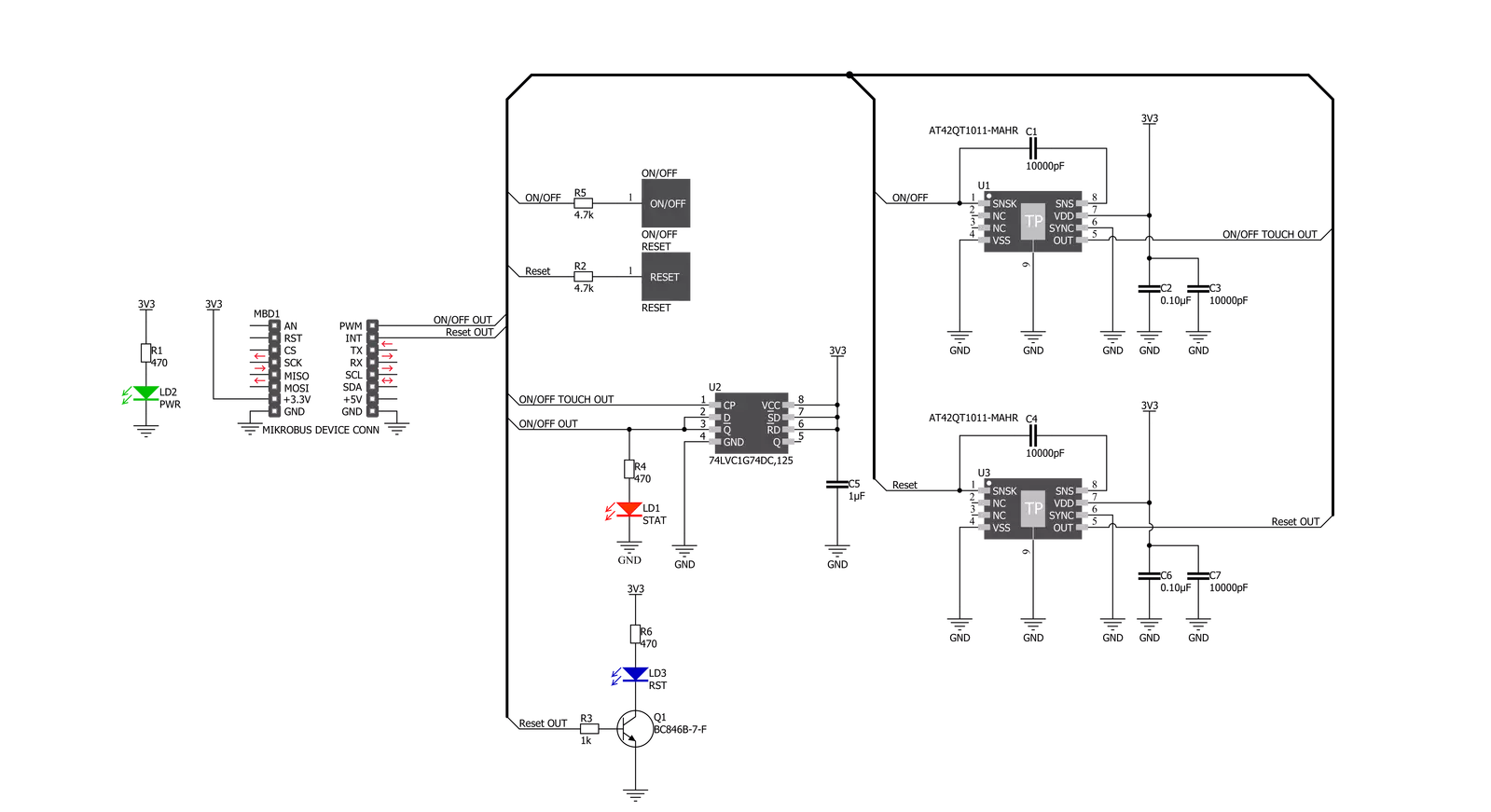
Power/Reset Click is based on the QT1011, a digital burst mode charge-transfer sensor capable of detecting proximity or touch from Microchip. This click board™ has two PCB pads to sense touch or proximity events. Besides the two touch-sensitive pads, Power/Reset click has two LEDs for the touch indication. The two touch pads use two separate QT1011 ICs, providing reliable touch-sensing functionality. The AT42QT1011 is a digital burst mode charge-transfer sensor capable of detecting proximity or touch, making it ideal for implementing touch controls. With the proper electrode and circuit design, the self-contained digital IC will project a touch or proximity field to several centimeters through any dielectric like glass, plastic, stone, ceramic, and even most kinds
of wood. It can also turn small metal-bearing objects into intrinsic sensors responsive to proximity or touch. This capability and its ability to self-calibrate can lead to entirely new product concepts. The QT1011 is designed for human interfaces like control panels, appliances, toys, lighting controls, or anywhere a mechanical switch or button may be found. It includes all hardware and signal processing functions necessary to provide stable sensing under various changing conditions. However, this click board™ is designed to serve as a power and reset capacitive switch panel board. Besides the QT1011, this click board™ contains 74LVC1G74 as well. It is a Single D-type flip-flop with set and reset. Because the output of the QT1011 is active-high upon detection, the
74LVC1G74 is triggered by the positive edge of the ON/OFF touchpad. It is wired in a cascade with the QT1011 in a way that ensures holding one logical state until the ON/OFF pad is pressed. Therefore, the ON/OFF pad acts like a switch, while the RESET pad acts like a button, which is suitable for most common purposes. The ON/OFF and RESET pad output signals are wired to the PWM and INT pins on the mikroBUS™, respectively. Besides that, the STAT and RST LEDs are wired parallel to the outputs to ensure a visible indication of the status of the pins. This Click board™ is designed to be operated only with a 3.3V logic level. A proper logic voltage level conversion should be performed before the Click board™ is used with MCUs with logic levels of 5V.

Features overview
Development board
Arduino UNO is a versatile microcontroller board built around the ATmega328P chip. It offers extensive connectivity options for various projects, featuring 14 digital input/output pins, six of which are PWM-capable, along with six analog inputs. Its core components include a 16MHz ceramic resonator, a USB connection, a power jack, an
ICSP header, and a reset button, providing everything necessary to power and program the board. The Uno is ready to go, whether connected to a computer via USB or powered by an AC-to-DC adapter or battery. As the first USB Arduino board, it serves as the benchmark for the Arduino platform, with "Uno" symbolizing its status as the
first in a series. This name choice, meaning "one" in Italian, commemorates the launch of Arduino Software (IDE) 1.0. Initially introduced alongside version 1.0 of the Arduino Software (IDE), the Uno has since become the foundational model for subsequent Arduino releases, embodying the platform's evolution.

Microcontroller Overview
MCU Card / MCU

Architecture
AVR
MCU Memory (KB)
32
Silicon Vendor
Microchip
Pin count
28
RAM (Bytes)
2048
You complete me!
Accessories
Click Shield for Arduino UNO has two proprietary mikroBUS™ sockets, allowing all the Click board™ devices to be interfaced with the Arduino UNO board without effort. The Arduino Uno, a microcontroller board based on the ATmega328P, provides an affordable and flexible way for users to try out new concepts and build prototypes with the ATmega328P microcontroller from various combinations of performance, power consumption, and features. The Arduino Uno has 14 digital input/output pins (of which six can be used as PWM outputs), six analog inputs, a 16 MHz ceramic resonator (CSTCE16M0V53-R0), a USB connection, a power jack, an ICSP header, and reset button. Most of the ATmega328P microcontroller pins are brought to the IO pins on the left and right edge of the board, which are then connected to two existing mikroBUS™ sockets. This Click Shield also has several switches that perform functions such as selecting the logic levels of analog signals on mikroBUS™ sockets and selecting logic voltage levels of the mikroBUS™ sockets themselves. Besides, the user is offered the possibility of using any Click board™ with the help of existing bidirectional level-shifting voltage translators, regardless of whether the Click board™ operates at a 3.3V or 5V logic voltage level. Once you connect the Arduino UNO board with our Click Shield for Arduino UNO, you can access hundreds of Click boards™, working with 3.3V or 5V logic voltage levels.

Used MCU Pins
mikroBUS™ mapper
Take a closer look
Click board™ Schematic
Step by step
Project assembly

Start by selecting your development board and Click board™. Begin with the Arduino UNO Rev3 as your development board.


Track your results in real time
Application Output
1. Application Output - In Debug mode, the 'Application Output' window enables real-time data monitoring, offering direct insight into execution results. Ensure proper data display by configuring the environment correctly using the provided tutorial.

2. UART Terminal - Use the UART Terminal to monitor data transmission via a USB to UART converter, allowing direct communication between the Click board™ and your development system. Configure the baud rate and other serial settings according to your project's requirements to ensure proper functionality. For step-by-step setup instructions, refer to the provided tutorial.

3. Plot Output - The Plot feature offers a powerful way to visualize real-time sensor data, enabling trend analysis, debugging, and comparison of multiple data points. To set it up correctly, follow the provided tutorial, which includes a step-by-step example of using the Plot feature to display Click board™ readings. To use the Plot feature in your code, use the function: plot(*insert_graph_name*, variable_name);. This is a general format, and it is up to the user to replace 'insert_graph_name' with the actual graph name and 'variable_name' with the parameter to be displayed.

Software Support
Library Description
This library contains API for Power/Reset Click driver.
Key functions:
powerreset_get_pwr- Power Check functionpowerreset_get_rst- Reset Check function
Open Source
Code example
The complete application code and a ready-to-use project are available through the NECTO Studio Package Manager for direct installation in the NECTO Studio. The application code can also be found on the MIKROE GitHub account.
/*!
 * \file
 * \brief Power Reset Click example
 *
 * # Description
 * Reads PWR and RST pin states and performs a control of the timer counter depending on the pressed button.
 *
 * The demo application is composed of two sections :
 *
 * ## Application Init
 * Initializes device and logger module, prints Initialization done message.
 *
 * ## Application Task
 * Checks the states of the PWR and RST pins and logs every change.
 *
 * \author MikroE Team
 *
 */
// ------------------------------------------------------------------- INCLUDES

#include "board.h"
#include "log.h"
#include "powerreset.h"

// ------------------------------------------------------------------ VARIABLES

static powerreset_t powerreset;
static log_t logger;

powerreset_state_t pwr_state;
powerreset_state_t rst_state;

powerreset_state_t new_pwr_state;
powerreset_state_t new_rst_state;

// ------------------------------------------------------ APPLICATION FUNCTIONS

void application_init ( void )
{
    log_cfg_t log_cfg;
    powerreset_cfg_t cfg;

    /**
     * Logger initialization.
     * Default baud rate: 115200
     * Default log level: LOG_LEVEL_DEBUG
     * @note If USB_UART_RX and USB_UART_TX
     * are defined as HAL_PIN_NC, you will
     * need to define them manually for log to work.
     * See @b LOG_MAP_USB_UART macro definition for detailed explanation.
     */
    LOG_MAP_USB_UART( log_cfg );
    log_init( &logger, &log_cfg );
    log_info( &logger, "---- Application Init ----" );

    //  Click initialization.

    powerreset_cfg_setup( &cfg );
    POWERRESET_MAP_MIKROBUS( cfg, MIKROBUS_1 );
    powerreset_init( &powerreset, &cfg );

    Delay_ms ( 100 );

    log_printf( &logger, "** Touch Button initialization done **\r\n");
    log_printf( &logger, "**************************************\r\n");
}

void application_task ( void )
{
    new_pwr_state = powerreset_get_pwr( &powerreset );
    new_rst_state = powerreset_get_rst( &powerreset );

    if ( new_pwr_state != pwr_state )
    {
        if ( new_pwr_state == POWERRESET_ACTIVE )
        {
            log_printf( &logger, "POWER ON\r\n" );
            Delay_ms ( 100 );
        }
        else if ( new_pwr_state == POWERRESET_INACTIVE )
        {
            log_printf( &logger, "POWER OFF\r\n" );
            Delay_ms ( 100 );
        }
        pwr_state = new_pwr_state;
    }

    if ( new_rst_state != rst_state )
    {
        if ( new_rst_state == POWERRESET_ACTIVE )
        {
            log_printf( &logger, "Reset occured!\r\n" );
            Delay_ms ( 100 );
        }
        rst_state = new_rst_state;
    }
}

int main ( void )
{
    /* Do not remove this line or clock might not be set correctly. */
    #ifdef PREINIT_SUPPORTED
    preinit();
    #endif

    application_init( );

    for ( ; ; )
    {
        application_task( );
    }

    return 0;
}

// ------------------------------------------------------------------------ END
Additional Support
Resources
Category:Capacitive


