Provide seamless touch detection and precise magnetic field sensing with IQS624 and ATmega328P
Connect with a single touch
Published Feb 14, 2024
Click board™
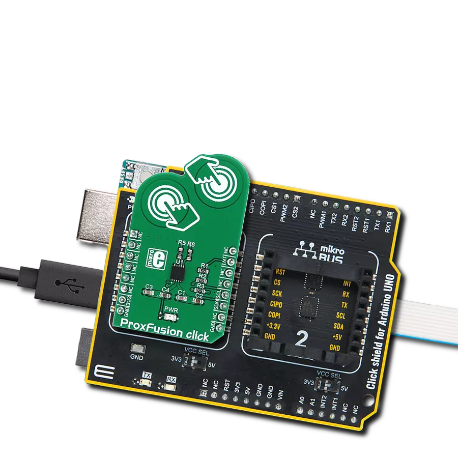
ProxFusion Click
Dev. board
Arduino UNO Rev3
Compiler
NECTO Studio
MCU
ATmega328P
Designed to enhance user interaction and control, this advanced sensor device empowers developers to create innovative products with touch-sensitive capabilities and accurate magnetic angle detection
A
A
Hardware Overview
How does it work?
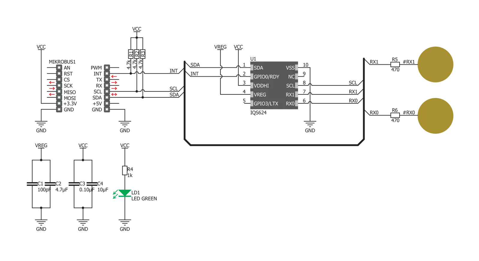
ProxFusion Click is based on the IQS624, a combined multi-sensor IC from Azoteq, including Hall-effect rotation sensing, dual-channel capacitive proximity or touch sensing, or single-channel inductive sensing. This IC features the proven ProxSense® engine, and it has many on-chip features that are used to process the sensor data, such as calculated angle rotation with 1° precision, Automatic Tuning Implementation (ATI), relative rotation angle, and more. All these functions process the sensor data before the final result is sent to the output in a human-understandable format. Besides these processed values, IQS624 can also send raw values on the output so that external processing can be applied. The board's design is reasonably simple since the IC encompasses all the required components on the chip. The I2C bus lines are pulled up to 3.3V with the resistors and the RDY pin from the IC, routed to the INT pin of the mikroBUS™. This pin can report an event when the device is set to work in the event mode via I2C. Otherwise, this pin is
used to indicate a communication window. After the host MCU initializes the communication by sending the valid I2C address of the IQS624 IC, it will respond with the ACK signal, and the RDY pin will be pulled to a LOW logic state to indicate an open communication window. I2C features a time-out that will reset the communication bus and the RDY pin, allowing MCU to use interrupts and break the I2C ACK signal polling loop. The capacitive touch sensing is accomplished by two onboard pads routed to two internal channels of the IQS624 sensor IC. All the calibration can be automatically done by writing to the corresponding ATI registers. This group of registers also contains settings for the capacitive touch threshold and the proximity threshold, as well as some additional general configuration settings for these sensors. Both of these channels can be configured independently. The other four channels of the IQS624 sensor are routed to the outputs of two on-chip Hall plates, which are used to detect a magnetic field rotation. The Hall-effect magnetic field measurement is a
measurement of the current through the Hall-effect sensor plates, generated by the magnetic field penetrating through each plate perpendicularly. Channels 2 and 4 are used to measure positive direction, while channels 3 and 5 are used to measure negative direction. The IC can use the differential data to provide the Hall-effect rotation UI element angle - or a magnet rotation angle, parallel to the click board™ surface. The raw input from the sensors is processed so it outputs comprehensible information at the output. Corresponding registers can be set to configure and receive the data from Hall-effect sensors. The working frequency of the device is 16MHz, and the maximum I2C clock speed is 400kHz. ProxFusion click can work in several different power-saving modes, depending on the design requirements. As explained above, the event mode can be set within the configuration registers. Otherwise, a streaming mode is active by default, and the information can be obtained whenever the RDY is triggered.


Features overview
Development board
Arduino UNO is a versatile microcontroller board built around the ATmega328P chip. It offers extensive connectivity options for various projects, featuring 14 digital input/output pins, six of which are PWM-capable, along with six analog inputs. Its core components include a 16MHz ceramic resonator, a USB connection, a power jack, an
ICSP header, and a reset button, providing everything necessary to power and program the board. The Uno is ready to go, whether connected to a computer via USB or powered by an AC-to-DC adapter or battery. As the first USB Arduino board, it serves as the benchmark for the Arduino platform, with "Uno" symbolizing its status as the
first in a series. This name choice, meaning "one" in Italian, commemorates the launch of Arduino Software (IDE) 1.0. Initially introduced alongside version 1.0 of the Arduino Software (IDE), the Uno has since become the foundational model for subsequent Arduino releases, embodying the platform's evolution.

Microcontroller Overview
MCU Card / MCU

Architecture
AVR
MCU Memory (KB)
32
Silicon Vendor
Microchip
Pin count
28
RAM (Bytes)
2048
You complete me!
Accessories
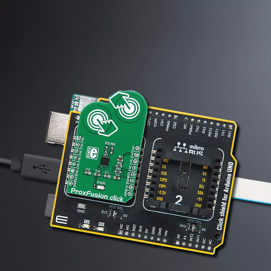
Click Shield for Arduino UNO has two proprietary mikroBUS™ sockets, allowing all the Click board™ devices to be interfaced with the Arduino UNO board without effort. The Arduino Uno, a microcontroller board based on the ATmega328P, provides an affordable and flexible way for users to try out new concepts and build prototypes with the ATmega328P microcontroller from various combinations of performance, power consumption, and features. The Arduino Uno has 14 digital input/output pins (of which six can be used as PWM outputs), six analog inputs, a 16 MHz ceramic resonator (CSTCE16M0V53-R0), a USB connection, a power jack, an ICSP header, and reset button. Most of the ATmega328P microcontroller pins are brought to the IO pins on the left and right edge of the board, which are then connected to two existing mikroBUS™ sockets. This Click Shield also has several switches that perform functions such as selecting the logic levels of analog signals on mikroBUS™ sockets and selecting logic voltage levels of the mikroBUS™ sockets themselves. Besides, the user is offered the possibility of using any Click board™ with the help of existing bidirectional level-shifting voltage translators, regardless of whether the Click board™ operates at a 3.3V or 5V logic voltage level. Once you connect the Arduino UNO board with our Click Shield for Arduino UNO, you can access hundreds of Click boards™, working with 3.3V or 5V logic voltage levels.

Used MCU Pins
mikroBUS™ mapper
Take a closer look
Click board™ Schematic
Step by step
Project assembly

Start by selecting your development board and Click board™. Begin with the Arduino UNO Rev3 as your development board.


Software Support
Library Description
This library contains API for ProxFusion Click driver.
Key functions:
proxfusion_get_touch- This function detects touch eventproxfusion_set_system_reg- This function sets system registerproxfusion_set_event_reg- This function select events
Open Source
Code example
The complete application code and a ready-to-use project are available through the NECTO Studio Package Manager for direct installation in the NECTO Studio. The application code can also be found on the MIKROE GitHub account.
/*!
 * \file
 * \brief ProxFusion Click example
 *
 * # Description
 * This demo-app reads and displays touch events using ProxFusion Click.
 *
 * The demo application is composed of two sections :
 *
 * ## Application Init
 * Configuring Clicks and log objects.
 * Settings the Click in the default configuration.
 *
 * ## Application Task
 * Checks if a new touch event occurred and prints(logs) event message on usbuart.
 *
 * \author Katarina Perendic
 *
 */
// ------------------------------------------------------------------- INCLUDES

#include "board.h"
#include "log.h"
#include "proxfusion.h"

// ------------------------------------------------------------------ VARIABLES

static proxfusion_t proxfusion;
static log_t logger;

// ------------------------------------------------------ APPLICATION FUNCTIONS

void application_init ( void )
{
    log_cfg_t log_cfg;  /**< Logger config object. */
    proxfusion_cfg_t proxfusion_cfg;  /**< Click config object. */

    /**
     * Logger initialization.
     * Default baud rate: 115200
     * Default log level: LOG_LEVEL_DEBUG
     * @note If USB_UART_RX and USB_UART_TX
     * are defined as HAL_PIN_NC, you will
     * need to define them manually for log to work.
     * See @b LOG_MAP_USB_UART macro definition for detailed explanation.
     */
    LOG_MAP_USB_UART( log_cfg );
    log_init( &logger, &log_cfg );
    log_info( &logger, " Application Init " );

    // Click initialization.
    proxfusion_cfg_setup( &proxfusion_cfg );
    PROXFUSION_MAP_MIKROBUS( proxfusion_cfg, MIKROBUS_1 );
    if ( I2C_MASTER_ERROR == proxfusion_init( &proxfusion, &proxfusion_cfg ) )
    {
        log_error( &logger, " Communication init." );
        for ( ; ; );
    }

    if ( PROXFUSION_ERROR == proxfusion_default_cfg ( &proxfusion ) )
    {
        log_error( &logger, " Default configuration." );
        for ( ; ; );
    }

    log_info( &logger, " Application Task " );
}

void application_task ( void )
{
    uint8_t touch = proxfusion_get_touch( &proxfusion );
    if ( 1 == touch )
    {
        log_printf( &logger, " Touch button 1 is pressed\r\n" );
    }
    else if ( 2 == touch )
    {
        log_printf( &logger, " Touch button 2 is pressed\r\n" );
    }
    else if ( 3 == touch )
    {
        log_printf( &logger, " Both touch buttons are pressed\r\n" );
    }
    Delay_ms ( 100 );
}

int main ( void )
{
    /* Do not remove this line or clock might not be set correctly. */
    #ifdef PREINIT_SUPPORTED
    preinit();
    #endif

    application_init( );

    for ( ; ; )
    {
        application_task( );
    }

    return 0;
}

// ------------------------------------------------------------------------ END
Additional Support
Resources
Category:Capacitive


