Create innovative solutions with advanced control features using IQS266 and ATmega328P
The art of intuitive control

Published Feb 14, 2024
Click board™
SwipeSwitch Click
Dev. board
Arduino UNO Rev3
Compiler
NECTO Studio
MCU
ATmega328P
To simplify interactions and improve accessibility, our solution leverages the power of capacitive touch, gesture recognition, and proximity sensing, providing users with a natural and responsive way to engage with their devices
A
A
Hardware Overview
How does it work?
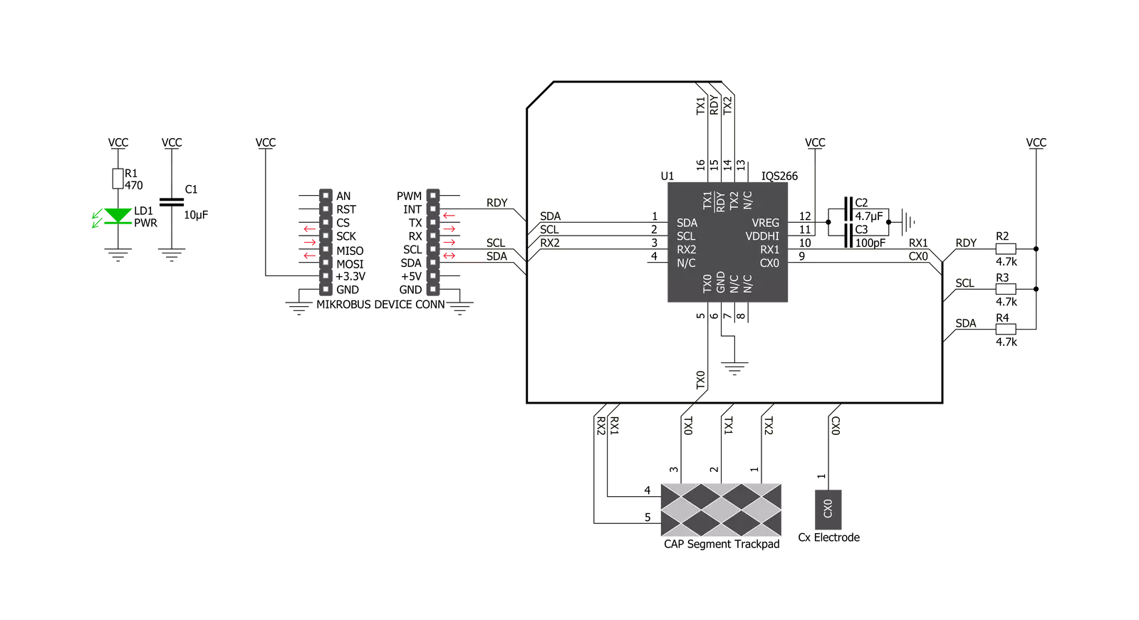
SwipeSwitch Click is based on the IQS266, an integrated trackpad controller circuit featuring ProxSense® and IQ Switch® technologies from Azoteq. This integrated touch controller features two receivers and three transmitters, allowing a 2x3 capacitive touch trackpad to be formed. Using a specific trace pattern on the PCB, the Click board™ can sense several swipe gestures, offering several different configuration parameters. By employing well-proven ProxSense® and IQ Switch® technologies, the IQS266 device can provide reliable touch detection in various environmental conditions. It uses the industry-standard I2C communication interface, with the additional RDY pin for the event signaling and communication protocol handshaking routines. Besides five capacitive touch-sensing electrodes, the IQS266 integrates a single proximity channel. This channel can wake the device from standby mode when the user approaches the touch panel, ensuring a low overall power consumption that way. CH0 is a dedicated proximity/touch channel, and it is treated as a separate channel group in the IQS266 settings. Both proximity and touch thresholds can be defined for this channel.
Automatic Tuning Implementation (ATI) ensures the optimal sensitivity of the sensing channels by monitoring the sampling values. The developer can set up the ATI targets for two groups of channels (channel 0 and channels 1-6). Once these targets are set, the ATI algorithm will try to match them, ensuring consistent behavior when used in various operating conditions. The ATI functionality can also be turned off/forced by the user to retune the sensor electrodes on demand. Otherwise, the IQS266 will automatically retune the electrodes whenever the counts drift outside a predefined ATI band to ensure optimal sensitivity. The RDY pin has two functions. It can be used as an interrupt event pin, signaling an event occurrence (when operated in the Event mode) or a "Data Ready" event. In this case, the RDY pin will be driven to a LOW logic level to signal an event, allowing it to generate an interrupt on the host MCU. However, the host MCU can pull the RDY pin down to initiate a communication window (communication protocol handshaking), requesting data from the device. The RDY pin is routed to the mikroBUS™ INT pin. The IQS266 can be set to operate in the Streaming or Event
modes. When operated in the Event mode, the RDY pin will indicate a communication window only after the selected event. There are several events: low power, swipe, tap, ATI, trackpad, touch, and proximity event. Each event is signalized by the RDY pin driven to a LOW logic level. More details about each event's RDY pin driving pattern can be found in the IQS266 datasheet. The IQS266 is very flexible, allowing many parameters to be tuned according to needs. These parameters include timeout periods for various modes (Zoom mode timeout, Low Power mode timeout, RDY timeout, and more), thresholds for various events and channels, some special sensing parameters, and such. The developer can set up these parameters by writing appropriate values to the registers of the IQS266 IC over the I2C interface. Please refer to the datasheet for a more detailed description of each register. However, the Click board™ is supported by a library of mikroSDK-compatible functions that simplify and speed up the development. It also comes with an example application that demonstrates their use.


Features overview
Development board
Arduino UNO is a versatile microcontroller board built around the ATmega328P chip. It offers extensive connectivity options for various projects, featuring 14 digital input/output pins, six of which are PWM-capable, along with six analog inputs. Its core components include a 16MHz ceramic resonator, a USB connection, a power jack, an
ICSP header, and a reset button, providing everything necessary to power and program the board. The Uno is ready to go, whether connected to a computer via USB or powered by an AC-to-DC adapter or battery. As the first USB Arduino board, it serves as the benchmark for the Arduino platform, with "Uno" symbolizing its status as the
first in a series. This name choice, meaning "one" in Italian, commemorates the launch of Arduino Software (IDE) 1.0. Initially introduced alongside version 1.0 of the Arduino Software (IDE), the Uno has since become the foundational model for subsequent Arduino releases, embodying the platform's evolution.

Microcontroller Overview
MCU Card / MCU

Architecture
AVR
MCU Memory (KB)
32
Silicon Vendor
Microchip
Pin count
28
RAM (Bytes)
2048
You complete me!
Accessories
Click Shield for Arduino UNO has two proprietary mikroBUS™ sockets, allowing all the Click board™ devices to be interfaced with the Arduino UNO board without effort. The Arduino Uno, a microcontroller board based on the ATmega328P, provides an affordable and flexible way for users to try out new concepts and build prototypes with the ATmega328P microcontroller from various combinations of performance, power consumption, and features. The Arduino Uno has 14 digital input/output pins (of which six can be used as PWM outputs), six analog inputs, a 16 MHz ceramic resonator (CSTCE16M0V53-R0), a USB connection, a power jack, an ICSP header, and reset button. Most of the ATmega328P microcontroller pins are brought to the IO pins on the left and right edge of the board, which are then connected to two existing mikroBUS™ sockets. This Click Shield also has several switches that perform functions such as selecting the logic levels of analog signals on mikroBUS™ sockets and selecting logic voltage levels of the mikroBUS™ sockets themselves. Besides, the user is offered the possibility of using any Click board™ with the help of existing bidirectional level-shifting voltage translators, regardless of whether the Click board™ operates at a 3.3V or 5V logic voltage level. Once you connect the Arduino UNO board with our Click Shield for Arduino UNO, you can access hundreds of Click boards™, working with 3.3V or 5V logic voltage levels.

Used MCU Pins
mikroBUS™ mapper
Take a closer look
Click board™ Schematic
Step by step
Project assembly

Start by selecting your development board and Click board™. Begin with the Arduino UNO Rev3 as your development board.


Track your results in real time
Application Output
1. Application Output - In Debug mode, the 'Application Output' window enables real-time data monitoring, offering direct insight into execution results. Ensure proper data display by configuring the environment correctly using the provided tutorial.

2. UART Terminal - Use the UART Terminal to monitor data transmission via a USB to UART converter, allowing direct communication between the Click board™ and your development system. Configure the baud rate and other serial settings according to your project's requirements to ensure proper functionality. For step-by-step setup instructions, refer to the provided tutorial.

3. Plot Output - The Plot feature offers a powerful way to visualize real-time sensor data, enabling trend analysis, debugging, and comparison of multiple data points. To set it up correctly, follow the provided tutorial, which includes a step-by-step example of using the Plot feature to display Click board™ readings. To use the Plot feature in your code, use the function: plot(*insert_graph_name*, variable_name);. This is a general format, and it is up to the user to replace 'insert_graph_name' with the actual graph name and 'variable_name' with the parameter to be displayed.

Software Support
Library Description
This library contains API for SliderSwitch Click driver.
Key functions:
swipeswitch_read_gestures- This function reads gesturesswipeswitch_read_x_coordinate- This function reads X coordinateswipeswitch_read_y_coordinate- This function reads Y coordinate
Open Source
Code example
The complete application code and a ready-to-use project are available through the NECTO Studio Package Manager for direct installation in the NECTO Studio. The application code can also be found on the MIKROE GitHub account.
/*!
 * \file
 * \brief SwipeSwitch Click example
 *
 * # Description
 * This Click is based on integrated touch controller featuring 2 receivers and 3 transmitters,
 * allowing a 2x3 capacitive touch trackpad to be formed. By using a specific trace pattern on the PCB,
 * the Click board is able to sense several different swipe gestures, offering several different configuration parameters.
 *
 * The demo application is composed of two sections :
 *
 * ## Application Init
 * Initialization and configuration of the chip for measurement
 *
 * ## Application Task
 * In the first test mode, it checks whether or not a new event ocurred (TAP or SWIPE).
 * If it did, it writes out data regarding that event via UART.
 * In the second test mode, X and Y coordinates are being read and logged via UART.
 *
 * \author MikroE Team
 *
 */
// ------------------------------------------------------------------- INCLUDES

#include "board.h"
#include "log.h"
#include "swipeswitch.h"

#define SWIPESWITCH_GESTURE_MODE        0
#define SWIPESWITCH_POSITION_MODE       1

// ------------------------------------------------------------------ VARIABLES

static swipeswitch_t swipeswitch;
static log_t logger;

static uint8_t x_coordinate = 0;
static uint8_t y_coordinate = 0;
static uint8_t old_x_coordinate = 0;
static uint8_t old_y_coordinate = 0;
static uint8_t events = 0;
static uint8_t gestures = 0;
static uint8_t display_mode;

// ------------------------------------------------------ APPLICATION FUNCTIONS

void application_init ( void )
{
    log_cfg_t log_cfg;
    swipeswitch_cfg_t cfg;

    /**
     * Logger initialization.
     * Default baud rate: 115200
     * Default log level: LOG_LEVEL_DEBUG
     * @note If USB_UART_RX and USB_UART_TX
     * are defined as HAL_PIN_NC, you will
     * need to define them manually for log to work.
     * See @b LOG_MAP_USB_UART macro definition for detailed explanation.
     */
    LOG_MAP_USB_UART( log_cfg );
    log_init( &logger, &log_cfg );
    log_info( &logger, "---- Application Init ----" );

    //  Click initialization.

    swipeswitch_cfg_setup( &cfg );
    SWIPESWITCH_MAP_MIKROBUS( cfg, MIKROBUS_1 );
    swipeswitch_init( &swipeswitch, &cfg );
    Delay_ms ( 300 );

    display_mode = SWIPESWITCH_GESTURE_MODE;

    if ( display_mode == SWIPESWITCH_GESTURE_MODE)
    {
        log_printf( &logger, "<<< GESTURE MODE >>> \r\n" );
    }
    else if ( display_mode == SWIPESWITCH_POSITION_MODE)
    {
        log_printf( &logger, "<<< POSITION MODE >>> \r\n" );
    }
}

void application_task ( void )
{
    if ( display_mode == SWIPESWITCH_GESTURE_MODE)
    {
        events = swipeswitch_read_events( &swipeswitch );
        gestures = swipeswitch_read_gestures( &swipeswitch );


        if ( ( events & ( SWIPESWITCH_EVENT_SWIPE ) ) != 0 )
        {
            if ( ( gestures & SWIPESWITCH_GESTURE_SWIPE_UP ) != 0 )
            {
                log_printf( &logger, "SWIPE UP \r\n" );
            }
            if ( ( gestures & SWIPESWITCH_GESTURE_SWIPE_DOWN ) != 0 )
            {
                log_printf( &logger, "SWIPE DOWN \r\n" );
            }
            if ( ( gestures & SWIPESWITCH_GESTURE_SWIPE_LEFT ) != 0 )
            {
                log_printf( &logger, "SWIPE LEFT \r\n" );
            }
            if ( ( gestures & SWIPESWITCH_GESTURE_SWIPE_RIGHT ) != 0 )
            {
                log_printf( &logger, "SWIPE RIGHT \r\n" );
            }
        }

        else if ( ( events & ( SWIPESWITCH_EVENT_TAP ) ) != 0 )
        {
            log_printf( &logger,"TAP \r\n" );
        }
    }
    else if ( display_mode == SWIPESWITCH_POSITION_MODE)
    {
        x_coordinate = swipeswitch_read_x_coordinate( &swipeswitch );
        y_coordinate = swipeswitch_read_y_coordinate( &swipeswitch );

        if ( ( x_coordinate != old_x_coordinate) || ( y_coordinate != old_y_coordinate ) )
        {
            log_printf( &logger,"Coordinate : (%u , %u)\r\n", (uint16_t) x_coordinate, (uint16_t) y_coordinate );

            old_x_coordinate = x_coordinate;
            old_y_coordinate = y_coordinate;
        }
    }
    Delay_ms ( 300 );
}

int main ( void )
{
    /* Do not remove this line or clock might not be set correctly. */
    #ifdef PREINIT_SUPPORTED
    preinit();
    #endif

    application_init( );

    for ( ; ; )
    {
        application_task( );
    }

    return 0;
}

// ------------------------------------------------------------------------ END
Additional Support
Resources
Category:Capacitive


